Main shaft for machining center machine

A machining center and spindle technology, which is used in metal processing machinery parts, metal processing equipment, manufacturing tools, etc., can solve the problem that the structure of the spindle device is not very ideal.

Inactive Publication Date: 2011-11-23
江南数控机床有限公司
View PDF6 Cites 2 Cited by
  • Summary
  • Abstract
  • Description
  • Claims
  • Application Information

AI Technical Summary

Problems solved by technology

The structure of above-mentioned ...

Method used


Image

  • Main shaft for machining center machine
  • Main shaft for machining center machine

Examples


Embodiment Construction

[0008] The present invention will be further described below in conjunction with the embodiments and accompanying drawings.

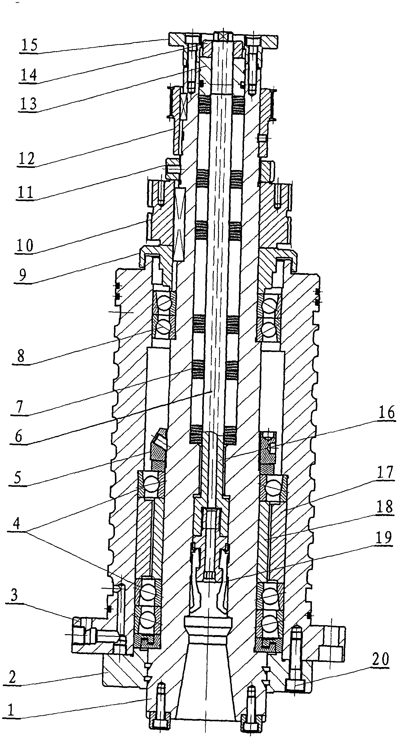
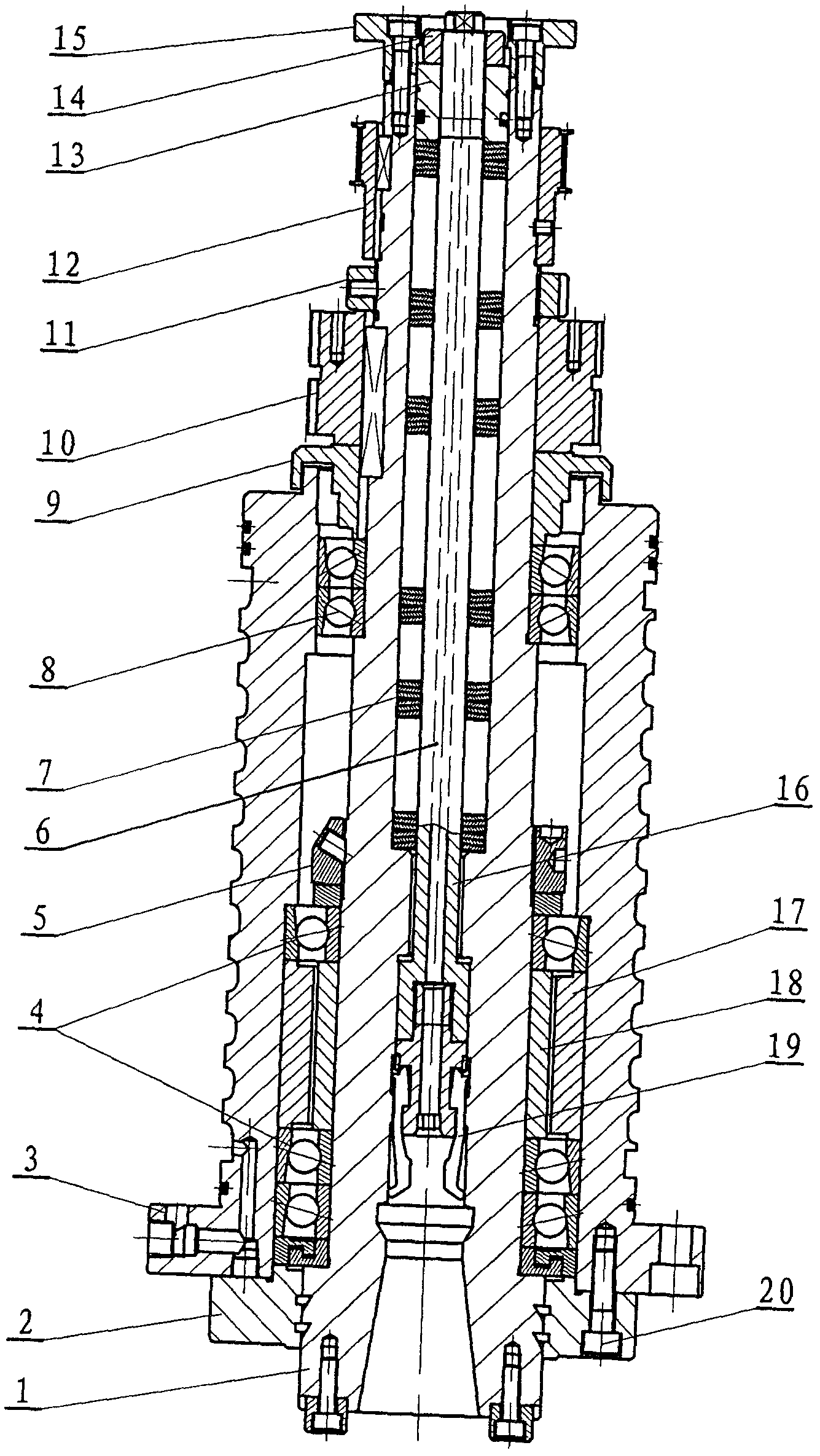
[0009] see figure 1 , a spindle for a machining center, which includes a shaft core 1, a shaft seat 3, the shaft core 1 is combined with the shaft seat 3 through 7014C bearing 4, 7012C bearing 8, and the front end cover 2 and the first spacer 17 pass through the flange The bolts 20 on the disk tighten the outer ring of the 7014C bearing 4, while the inner ring of the 7014C bearing 4 is fixed on the shaft core 1 through the first lock nut 5 and the second spacer 18, and the outer ring of the 7012C bearing 8 does not The inner ring is fixed on the shaft core 1 through the second lock nut 11, the first circular arc toothed pulley 10, and the dust cover 9, the ejector rod 16 is installed in the shaft core 1, and the four-petal claw 19 is installed on the top Under the rod 16, the ejector rod 16 bears the upward force of the disc spring 7 through the nut 13...


PUM


Abstract

The invention discloses a main shaft for a machining center machine, comprising a shaft core and a shaft seat, wherein the shaft core is combined together with the shaft seat through a 7014C bearing and a 7012C bearing; an outer ring of the 7014C bearing is pressed by using a front end cover and a first spacer bush through bolts on a ring flange; an inner ring of the 7014C bearing is fixed on the shaft core through a first locking nut and a second spacer bush; an outer ring of the 7012C bearing is not fixed; an inner ring of the 7012C bearing is fixed on the shaft core through a second locking nut, a first circular-arc toothed belt pulley and a dust resistant cover; an ejector rod is arranged in the shaft core; a four-valve jaw is arranged below the ejector rod; the ejector rod bears an upward action force of a disc spring through a nut and then transmits the upward action force to the four-valve jaw; the nut and a third locking nut are mutually fastened; the shaft core inputs a torque through the first circular-arc toothed belt pulley; and the first circular-arc toothed belt pulley and the second circular-arc toothed belt pulley are fixed on the shaft core and are positioned above the second locking nut. Compared with the prior art, the main shaft has a more reasonable structure.

Description

technical field [0001] The invention relates to a spindle, in particular to a spindle for a machining center. Background technique [0002] In CNC machine tools, whether it is a CNC lathe, drilling machine or milling machine, the spindle is the most critical component and plays a vital role in the accuracy of the machine tool. A Chinese patent once disclosed a "machining center machine spindle" (China, announcement number CN2838816Y, announcement date on November 22, 2006), which includes a main shaft seat, a main shaft in the main shaft seat, and a complete set of broaching claws in the main shaft , the tool handle in the whole group of broaching claws, the lower ball bearing, the thrust bearing, the upper ball bearing, the pulley, the upper cover of the main shaft seat on the upper end face of the main shaft seat, and the lower end of the main shaft seat on the lower end face of the main shaft seat The cover and the water throwing ring at the lower end of the main shaft, ...

Claims


Application Information

Patent Timeline
IPC IPC(8): B23B19/02B23Q3/00
Inventor 施建南
Owner 江南数控机床有限公司
Why Eureka
Try Eureka