Method for processing back-spraying hole in shell of rocket chamber by using conventional boring machine

A combustion chamber and reverse injection hole technology, which is used in boring/drilling, metal processing equipment, metal processing machinery parts, etc., can solve the problems of expensive, difficult to process high-precision reverse injection holes, etc. cost effect

Inactive Publication Date: 2011-11-23
湖北三江航天江北机械工程有限公司
View PDF4 Cites 12 Cited by
  • Summary
  • Abstract
  • Description
  • Claims
  • Application Information

AI Technical Summary

Problems solved by technology

[0004] At present, to process the four high-precision anti-spray holes at the front end of the rocket combustion chamber shell, an expensive CNC boring machin

Method used


Image

  • Method for processing back-spraying hole in shell of rocket chamber by using conventional boring machine
  • Method for processing back-spraying hole in shell of rocket chamber by using conventional boring machine
  • Method for processing back-spraying hole in shell of rocket chamber by using conventional boring machine

Examples


Embodiment 1

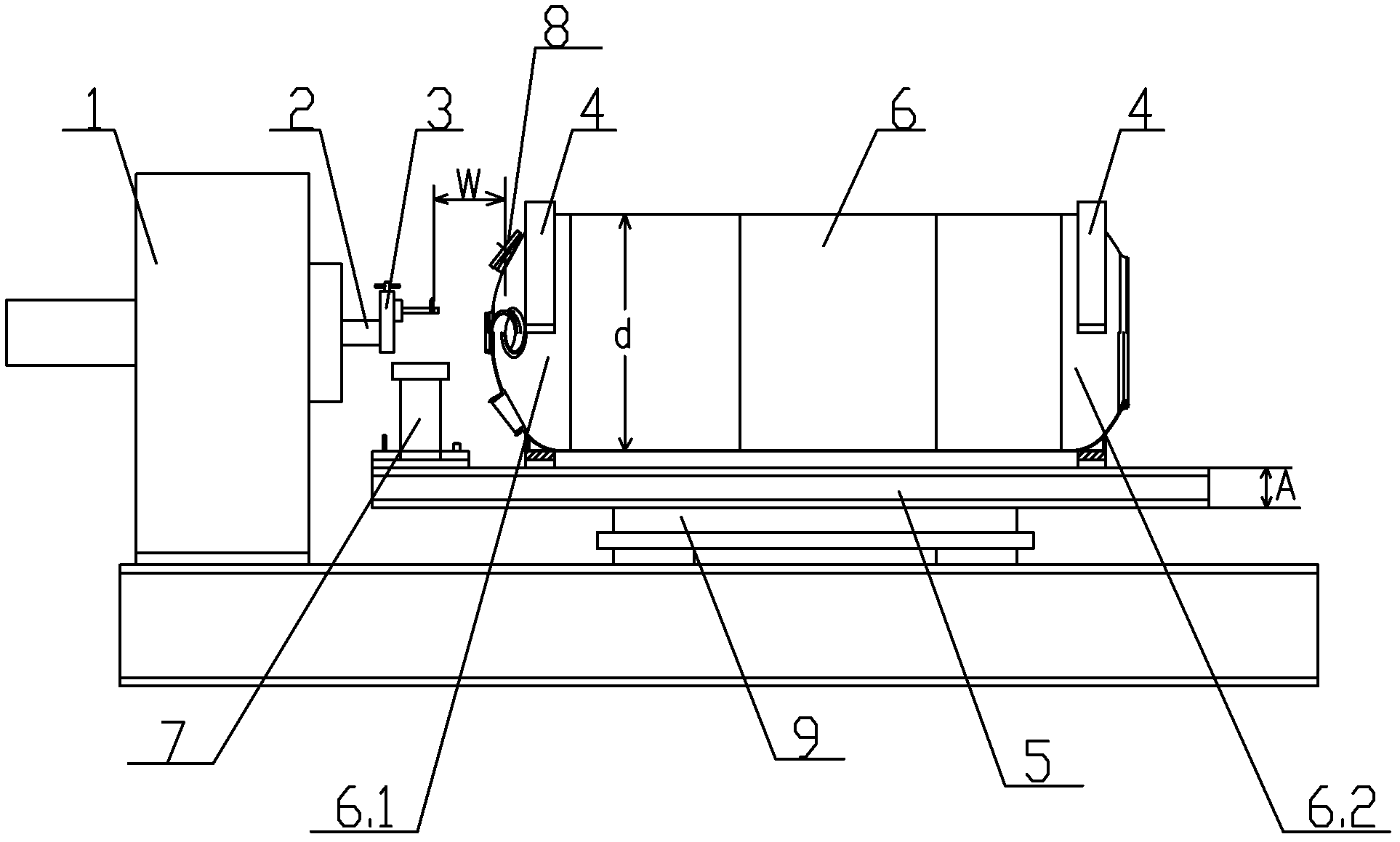
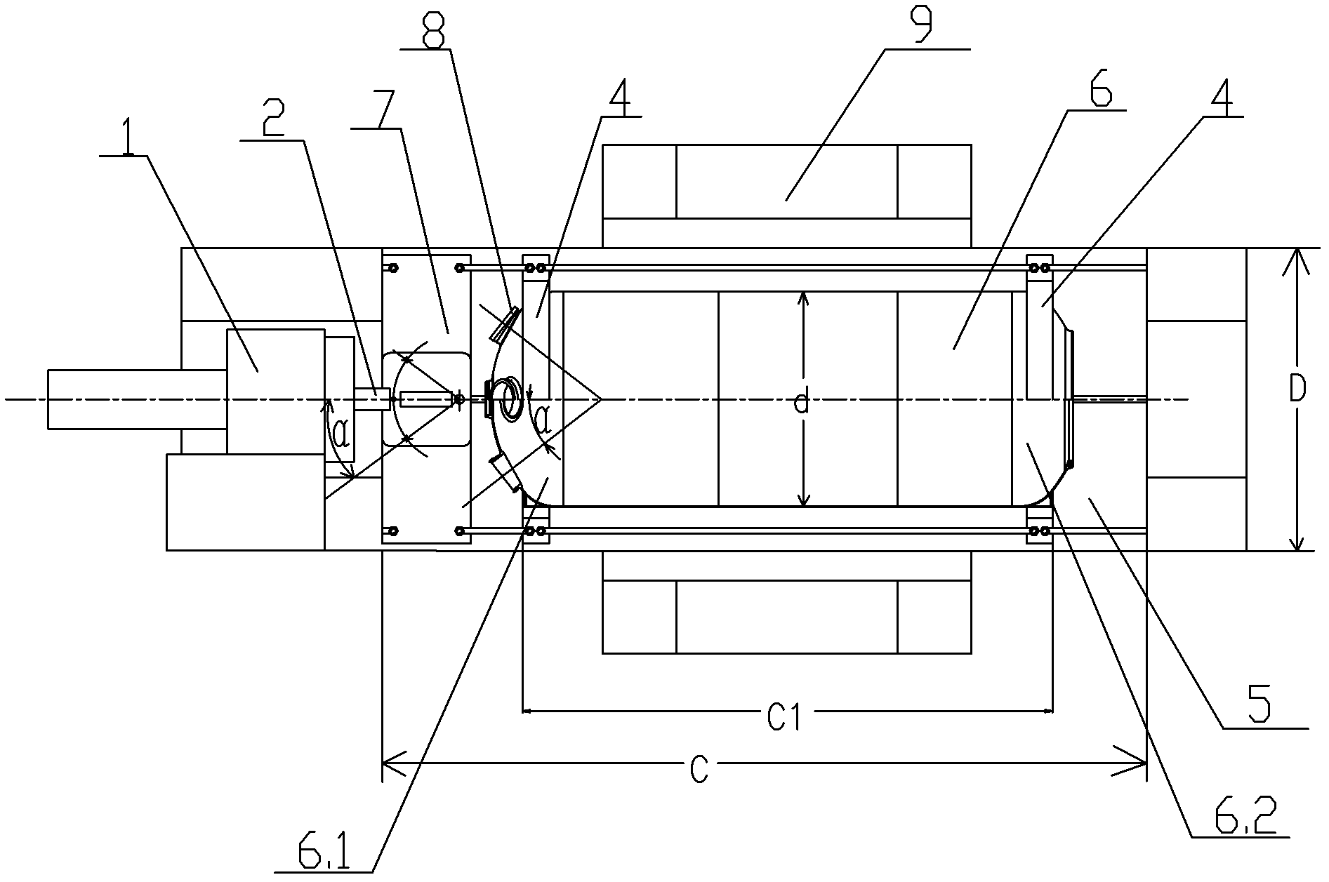
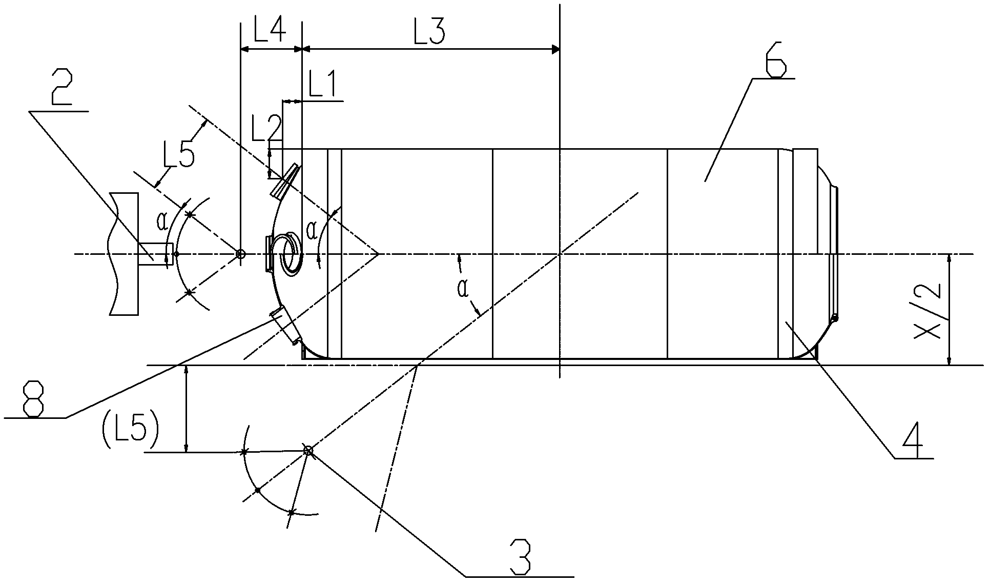
[0055] For a certain aircraft Φ880mm×5000mm rocket combustion chamber casing 6, the outer diameter of the front skirt 6.1 is d=880mm. The included angle between the anti-spray hole 8 and the axis center of the rocket combustion chamber casing 6 is α=38°, and the distance L between the center of the end face of the anti-spray hole 8 and the end face of the front skirt 6.1 1 =82.8mm, the distance L from the center of the end surface of the anti-spray hole 8 to the outer circle of the front skirt 6.1 2 = 125.25 mm. The distance L from the center of rotation of the horizontal worktable 9 to the end face of the front skirt 6.1 3 =2500mm. The length C=5600mm of the special platform 5, the width E=1250mm of the special platform 5, and the thickness A=250mm of the special platform 5. The distance B=100mm from the tangent line of the inner arc surface of the bracket base 4.3 lower end of the special bracket 4 to the lower end bottom surface of the bracket base 4.3. The distance L f...

Embodiment 2

[0068] For a certain aircraft Φ1200mm×6000mm rocket combustion chamber casing 6, the outer diameter of the front skirt 6.1 is d=1200mm. The angle between the anti-spray hole 8 and the axis center of the rocket combustion chamber casing 6 is α = 40°, and the distance L between the center of the end face of the anti-spray hole 8 and the end face of the front skirt 6.1 1 =136.3mm, the distance L from the center of the end surface of the anti-spray hole 8 to the outer circle of the front skirt 6.1 2 = 171.7mm. The distance L from the center of rotation of the horizontal worktable 9 to the end face of the front skirt 6.1 3 = 3000mm. The length C=6600mm of special-purpose platform 5, the width E=1400mm of special-purpose platform 5, the thickness A=300mm of special-purpose platform 5, the distance from the tangent line of the inner arc surface of the support base 4.3 lower end of the special-purpose support 4 to the support base 4.3 lower end bottom surface B=120mm. The distance...


PUM


Abstract

The invention discloses a method for processing a back-spraying hole in a shell of a rocket chamber by using a conventional boring machine. The method comprises the following steps of: (1) aligning and assembling a special tool; (2) aligning and assembling the shell; (3) aligning a space angle of the back-spraying hole; (4) aligning the space location of the back-spraying hole; (5) processing a No.1 back-spraying hole; (6) aligning and processing a No. 3 back-spraying hole; (7) aligning a No.2 back-spraying hole; and (8) aligning and processing No.2 and No.4 back-spraying holes. By adopting aseries of special aligning and clamping tools, the back-spraying holes in the shell of the rocket chamber are processed by using the conventional boring machine, the processing precision is high, andthe requirement for product designing precision is completely met; compared with processing by using an imported high-precision numerical controlled boring machine, the processing by using the methodprovided by the invention has the advantage that the equipment cost is remarkably reduced.

Description

technical field [0001] The invention relates to the processing technology of rocket combustion chamber casings, in particular to a method for processing anti-spray holes on rocket combustion chamber casings with a common boring machine. Background technique [0002] The solid rocket motor is the power device of the aerospace vehicle, which is composed of the main parts such as the combustion chamber, the propellant grain, the nozzle, and the igniter. The combustor casing is a key part of the solid rocket motor system, which provides power to the vehicle through the combustion of propellant. There are four evenly distributed anti-spray joints with anti-spray holes on the front head of the shell. The thrust termination mechanism is installed in the anti-spray holes, and the outer thread is connected with the guide pipe. When the aircraft arrives at the predetermined position, the computer on the bomb sends out a detonation command, the thrust termination mechanism is detonate...

Claims


Application Information

Patent Timeline
IPC IPC(8): B23P15/00B23B41/00B23B35/00B23Q3/02B23Q3/08B23Q3/12B23Q3/16
Inventor 韩庆波汪训杰余天雄
Owner 湖北三江航天江北机械工程有限公司
Why Eureka
Try Eureka