Automobile door hinge clamp

A door hinge and fixture technology, applied in the direction of manufacturing tools, workpiece clamping devices, etc., can solve the problems of increasing the production cost of manufacturers, complicated procedures and cumbersome devices, and achieve the effect of improving work efficiency.

Inactive Publication Date: 2011-11-23
HEFEI XINGKE PETROCHEM EQUIP TECH
View PDF6 Cites 8 Cited by
  • Summary
  • Abstract
  • Description
  • Claims
  • Application Information

AI Technical Summary

Problems solved by technology

Stamping hinges are generally composed of a main hinge, a secondary hinge, and a shaft sleeve and a pivot pin used to connect the two. In the past, the assembly method of stamping hinges was to manually assemble the above parts. Needless to say, the productivity is low, and the yield rate also lower
At present, some countries have begun to use hinge assembly production lines to realize the mechanized assembly of automobile door hinges. However, if the hinge assembly wants to be mechanized, it is necessary to use fixtures to achieve accurate positioning and clamping of the parts to be assembled. The existing fixtures In actual work, they are directly fixed on the corresponding process position. When the process is switched, the assembly can only be loaded and unloaded on each fixture by the cooperative operation of the manipulator. That is to say, each time the manipulator reassembles the parts to be assembled. When clamping, the positioning and assembly references of the previous process are destroyed, so that precise positioning cannot be achieved at all, let alone accurate assembly. Resetting and positioning the positioning benchmark and using a large number of sensors to realize timely monitoring not only complicate the device and cumbersome the process, but also greatly increase the production cost of the manufacturer. It has a high error rate, a high failure downtime rate, and extremely frequent maintenance

Method used


Image

  • Automobile door hinge clamp
  • Automobile door hinge clamp
  • Automobile door hinge clamp

Examples


Embodiment Construction

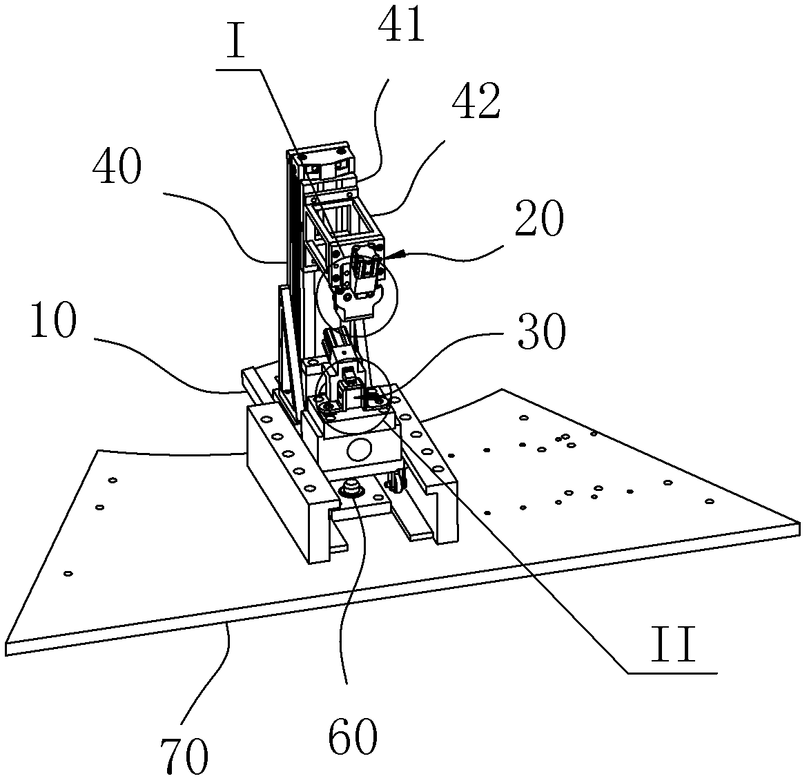
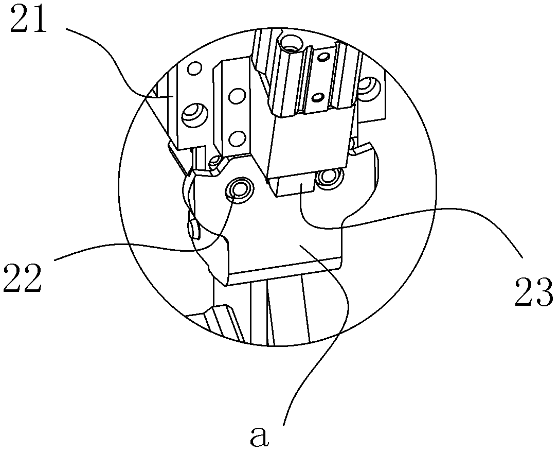
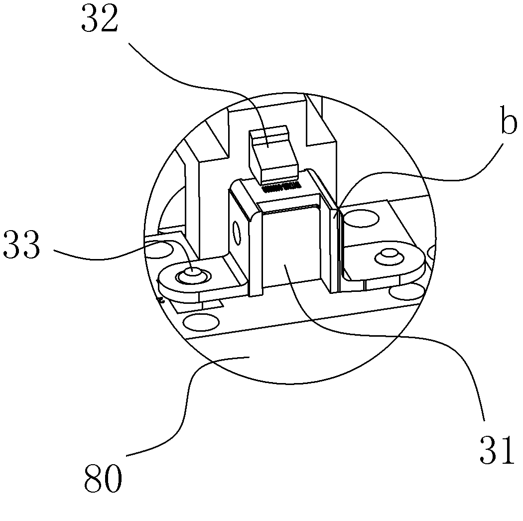
[0014] An automobile door hinge clamp, the clamp includes a base 10 and a clamping portion arranged on the base 10 for clamping the hinge, the clamping portion includes a first clamping portion 20 for clamping the main hinge And the second clamping part 30 for clamping the secondary hinge, the axes of the pin shaft holes of the two hinges clamped on the clamping part are parallel to each other, and the clamp has two position states, one of which is two clamps The holding parts are separated from each other and the corresponding hinge parts are installed separately. Another position state is that the two holding parts move relative to each other along the plane formed by the axes of the two parallel pin shaft holes, and finally guide the axes of the pin shaft holes of the two hinges to coincide and make Both of the above are in the correct assembly position, as in figure 1 and Figure 7-8 shown.

[0015] For ease of understanding, the structure of one of the assembly machines...


PUM


Abstract

The invention belongs to the technical field of automobile parts assembling, and in particular relates to an automobile door hinge clamp. The automobile door hinge clamp comprises a base and a clamping part arranged on the base for clamping a hinge; the clamping part comprises a first clamping part for clamping a main hinge and a second clamping part for clamping a secondary hinge; axial lines ofpin shaft holes of two hinges clamped on the clamping part are parallel to each other; the clamp has two position states, one is that two clamping parts are separated from each other and independently provided with a corresponding hinge part, and the other is that two clamping parts can relatively move along a plane formed by two parallel pin shaft hole axial lines so that the pin shaft axial lines of two hinges can be guided to be superposed with each other, and the two hinges can be positioned in correct assembling positions to be reliably positioned and clamped; the working efficiency is greatly improved, the structure is simple and convenient for operation and maintenance.

Description

technical field [0001] The invention belongs to the technical field of assembly of automobile parts, and in particular relates to an automobile door hinge clamp. Background technique [0002] Automobile door hinge is a general term for the connection between the body and the door, which can rotate around the same axis in the up and down direction and combine with each other. According to the hinge manufacturing process, it can be roughly divided into stamping hinges and profile hinges. Among them, stamping hinges are widely used because of their simple form, good craftsmanship and low cost. Stamping hinges are generally composed of a main hinge, a secondary hinge, and a shaft sleeve and a pivot pin used to connect the two. In the past, the assembly method of stamping hinges was to manually assemble the above parts. Needless to say, the productivity is low, and the yield rate Also lower. At present, some countries have begun to use hinge assembly production lines to realize...

Claims


Application Information

Patent Timeline
Patent Type & Authority Applications(China)
IPC IPC(8): B25B11/02
Inventor 王岚
Owner HEFEI XINGKE PETROCHEM EQUIP TECH
Why Eureka
Try Eureka