
Silica gel calendering compounding machine

A composite machine and calendering technology, which is applied in the field of calendering composite machines, can solve the problems of large power consumption, single speed ratio, and low production efficiency, and achieve the effects of increased production efficiency, reduced motor power, and low power consumption

Inactive Publication Date: 2011-11-23
SUZHOU DOFLY M & E TECH
View PDF6 Cites 1 Cited by
  • Summary
  • Abstract
  • Description
  • Claims
  • Application Information

AI Technical Summary

Problems solved by technology

[0003] (1) poor quality
[0004] When producing thicker products (thickness above 1-2mm), there will be a large number of air bubbles in the produced product, and different degrees of poor quality will occur depending on the thickness. Although various measures are taken to eliminate air bubbles, quality defects cannot be solved. It is fundamentally overcome and cannot meet the quality requirements of silicone products in the electronics-related industries. The reason is that the existing calender drive device is driven by a single motor through a reducer and driven by gears. The speed ratio between the rollers is single and cannot be adjusted. Adapt to the matching requirements of different thickness silicone products for the mutual speed ratio of each roller;
[0005] (2) Low efficiency
[0006] Due to the use of a single motor drive, the speed ratio between the rollers is single and cannot be adjusted. When producing products with different thicknesses, especially thicker products, in order to meet the quality requirements, the production speed cannot be too fast, so the actual production efficiency is low;
[0007] (3) High power consumption
[0008] Existing calenders generally use electromagnetic speed-regulating motors and cycloidal pinwheel reducers as driving devices. Since the motors have been running continuously at the rated speed, the actual power consumption = motor power + other power, and the power consumption is large;
[0009] (4) Waste of labor
[0010] The existing calender does not have an integrated feeding device and tension control, and it needs to be equipped with a feeding rack and manual feeding during compound production, which is a waste of labor;
[0011] (5) Large footprint
[0012] The existing calender adopts integral casting frame base and transmission base, no matter whether the motor is placed parallel to the roller or vertically, it will occupy a large area

Method used


Image

  • Silica gel calendering compounding machine
  • Silica gel calendering compounding machine
  • Silica gel calendering compounding machine

Examples


Embodiment Construction

[0030] Preferred embodiment of the present invention is described in detail below in conjunction with accompanying drawing:

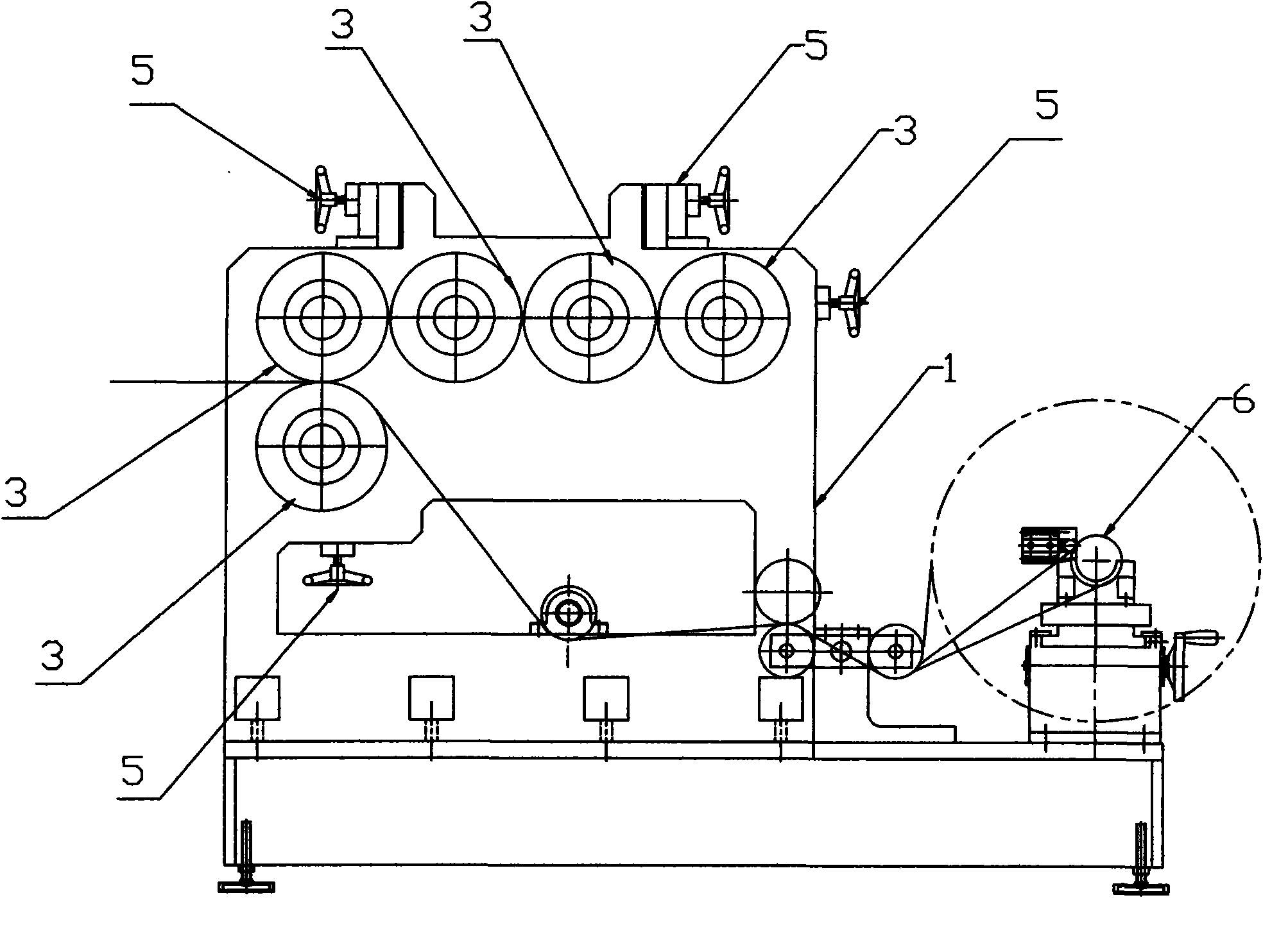
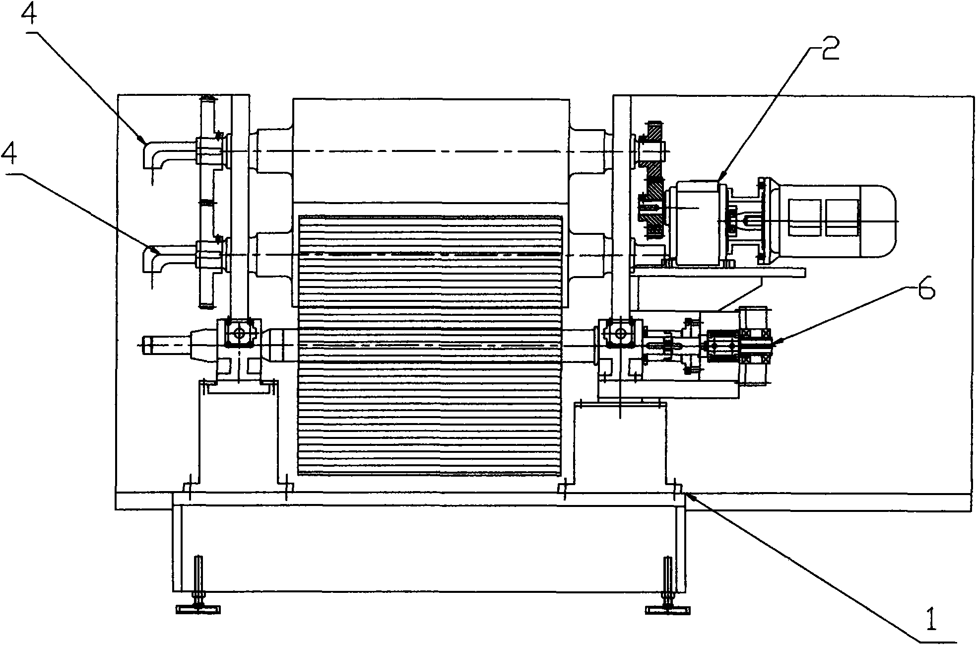
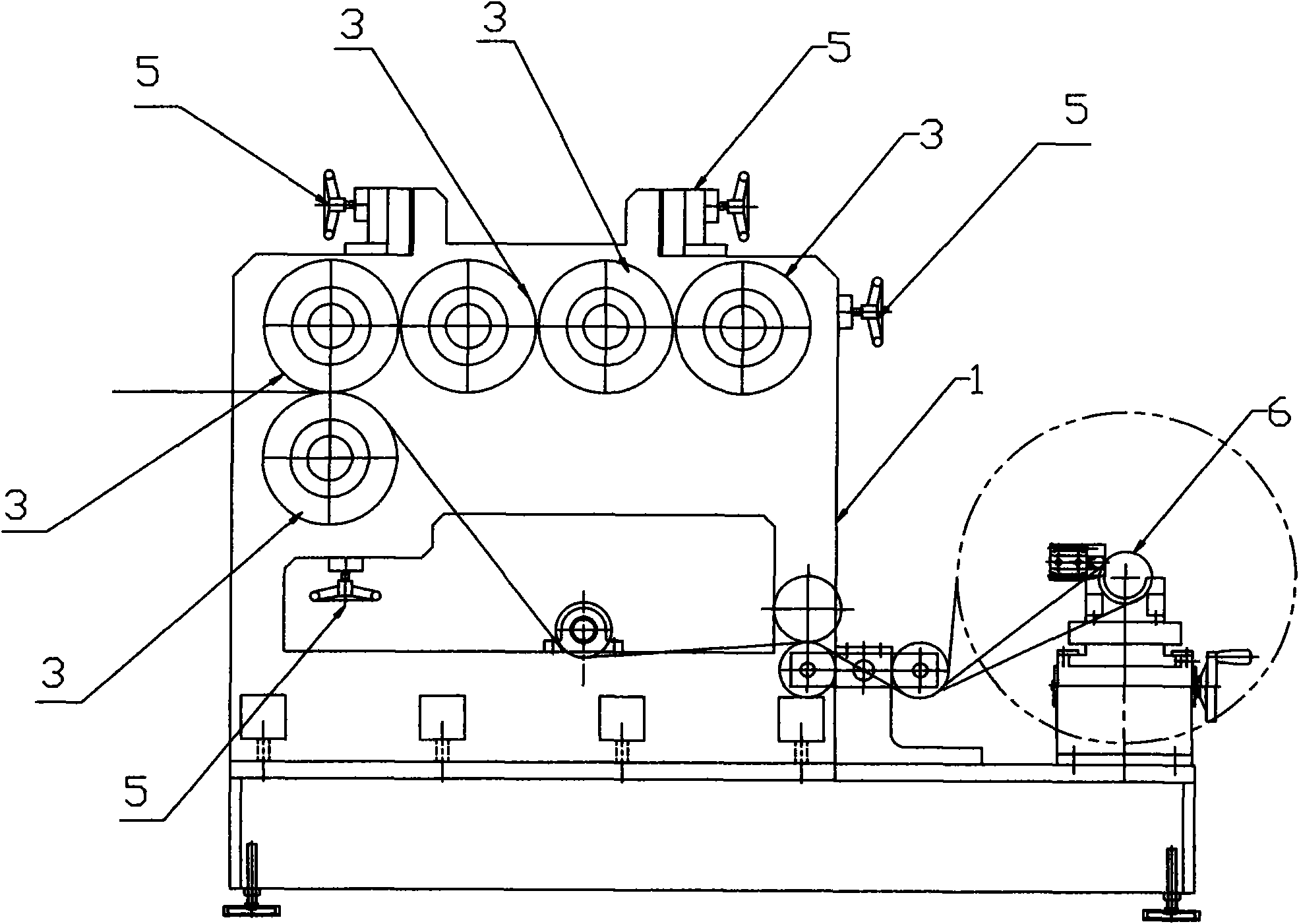
[0031] Such as figure 1 , 2 As shown, the silicone calender compound machine includes a frame 1 and five rollers 3, the rollers 3 are connected to the frame 1 through bearing seats, and the five rollers 3 are arranged in an inverted "L" shape, and the adjacent rollers 3 There is a roller gap adjustment device 5 between them, and each roller 3 is connected with an independent frequency conversion motor 2, that is, each roller 3 is driven by a frequency conversion motor 2 to rotate independently, and the frequency conversion motor 2 is a frequency conversion gear reduction motor . The silica gel calender compound machine also includes an integrated discharging system 6, which is located on the frame 1. In addition, the roller 3 is also provided with a roller temperature regulating device, and the roller temperature regulating device is opposite to the r...


PUM


Abstract

The invention discloses a silica gel calendering compounding machine, comprising a rack and five rollers, wherein, the rollers are connected with the rack through a bearing pedestal, and each roller is respectively connected with an independent variable frequency motor. According to the invention, a plurality of variable frequency motors are used to independently drive each roller to enable the speed ratio among rollers to be arbitrary ratio, cooperate the reasonable collocation of distance between rollers and generate certain buildup between rollers, so that the quality defect of bubbles carried in the products can be solved, and the advantages of low electricity consumption, small volume, high production efficiency, labor saving and the like of the silica gel calendering compounding machine are achieved.

Description

technical field [0001] The invention relates to a calender compound machine, in particular to a silica gel calender compound machine. Background technique [0002] Existing calenders for the rubber industry. Mainly used for the production of silica gel (silicone) sheets, the composite production of silica gel (silicone) sheets and film / cloth, and the production or composite production of rubber sheets below Shore 50 degrees. The existing calender consists of two or more rollers arranged in a certain form, mainly composed of rollers, racks, roller distance adjustment devices, roller temperature adjustment devices, transmission devices, lubrication systems, feeding systems and control system etc. There are following shortcoming and deficiency in existing calender: [0003] (1) poor quality [0004] When producing thicker products (thickness above 1-2mm), there will be a large number of air bubbles in the produced product, and different degrees of poor quality will occur dep...

Claims


Application Information

Patent Timeline
IPC IPC(8): B29C43/24B29C43/46B29C43/58B29C43/34
CPCY02P70/10
Inventor 李魁立
Owner SUZHOU DOFLY M & E TECH
Learn More