Integrated device for impurity removal pulping and charging of oil sludge

A technology for pulping and oil sludge, applied in sludge treatment, chemical instruments and methods, water/sludge/sewage treatment, etc., can solve problems such as inability to integrate feeding materials, inability to automatically clean and discharge, and increase in production costs, and achieve The effect of reducing manufacturing cost and troubleshooting rate, saving manpower, and stabilizing the mixing ratio

Active Publication Date: 2013-01-02
DAQING PETROLEUM ADMINISTRATION +1
View PDF7 Cites 0 Cited by
  • Summary
  • Abstract
  • Description
  • Claims
  • Application Information

AI Technical Summary

Problems solved by technology

At present, the general oil sludge recycling and harmless treatment process first adopts semi-mechanized filtration, and the oil sludge is sent to the filter tank through the transmission device, and a sharp-toothed auger is installed in the filter tank. Through the rotation of the auger and the heat Washing with water softens, dissolves and dilutes the oil sludge. The small particles in the diluted oil sludge fall through the screen at the bottom of the filter tank and fall into the lower processing device. The large particles of impurities screened out remain in the filter tank and cannot be cleaned automatically. A lot of manual cleaning is required, which is labor-intensive and inefficient
Sometimes there are large pieces of impurities stuck to the auger, which requires repairing the equipment, resulting in increased production costs
At the same time, the sieved oil sludge has not undergone further pulping treatment. Since the oil sludge is not completely dispersed, it cannot be integrated into the subsequent processing device in a stable and controllable way, and it is difficult to make the harmless treatment of oil sludge resources continue and stably produce

Method used


Image

  • Integrated device for impurity removal pulping and charging of oil sludge
  • Integrated device for impurity removal pulping and charging of oil sludge

Examples


Embodiment Construction

[0011] The present invention will be further described below in conjunction with accompanying drawing:

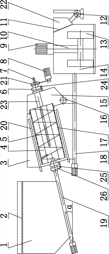
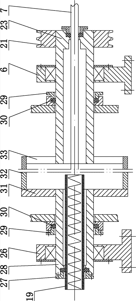
[0012] Depend on Figure 1 to Figure 2 As shown, the integrated device for sludge removal, pulping and feeding includes feed hopper 1, screw conveyor one 19, impurity removal tank 3, impurity removal drum 4, screw conveyor two 18, screw conveyor three 16, High-pressure hot water injection pipe one 7, high-pressure hot water injection pipe two 20, impurity removal drum driving mechanism 8, pulper 14, pulping driving mechanism 9, roller 13 and mud pump 12, wherein the feed hopper 1 Screw conveyor one 19 is installed at the bottom, and impurity removal drum 4 is housed in the impurity removal tank 3, and a debris pool 15 is provided, and screw conveyor three 16 is installed on the bottom of the debris pool 15, and the discharge of screw conveyor one 19 The end is located in the impurity removal drum 4, the bottom of the impurity removal tank 3 is equipped with a screw conveyo...


PUM


Abstract

The invention relates to an integrated device for removing impurities, making pulp, and feeding materials used in the front-end treatment of the harmless treatment of oil sludge resources in oil fields. It mainly solves the problems of unstable front-end treatment process of existing oil sludge, uneven pulping and uncontrollable feeding quantity to the follow-up. The device includes a feed hopper, an impurity removal tank, a pulper and a mud pump. A screw conveyor 1 is installed at the bottom of the feed hopper, and the discharge end of the screw conveyor 1 is located in the impurity removal tank. The impurity removal tank The bottom of the bottom is equipped with screw conveyor two, and the screw conveyor two communicates with the pulp maker, and the inlet of the mud pump communicates with the liquid sump in the pulp maker. The device removes impurities and makes pulp by screw conveyor. The flow rate can be controlled by adjusting the rotation speed of the screw conveyor. The amount of hot water can be controlled by controlling the flow rate of hot water, so that the production process is stable and controllable.

Description

technical field [0001] The invention relates to front-end treatment in oilfield oil sludge recycling and harmless treatment, in particular to an integrated device for removing impurities, pulping, and feeding the oil sludge. Background technique [0002] In oil field production, the amount of oil sludge produced is gradually increasing. With the increasing emphasis on environmental protection, the oil sludge produced in oil field production must be recycled and harmlessly treated. Before sludge recycling and harmless treatment, it is usually necessary to remove impurities and make oil sludge, and then carry out subsequent recycling and harmless treatment. At present, the general oil sludge recycling and harmless treatment process first adopts semi-mechanized filtration, and the oil sludge is sent to the filter tank through the transmission device, and a sharp-toothed auger is installed in the filter tank. Through the rotation of the auger and the heat Washing with water sof...

Claims


Application Information

Patent Timeline
Patent Type & Authority Patents(China)
IPC IPC(8): C02F11/00
Inventor 郭富太刘新飚姜亦坚娄彦文王纲杜海涛
Owner DAQING PETROLEUM ADMINISTRATION
Why Eureka
Try Eureka