Power distribution device for rotating target

A power distribution device and rotating target technology, applied in the direction of flexible/rotatable wire connectors, circuits, electrical components, etc., can solve the problems of increased manufacturing and maintenance costs, difficult maintenance, and the inability to separate the integrated structure. Ease of maintenance and replacement, smooth rotation

Inactive Publication Date: 2011-11-23
黄峰
View PDF4 Cites 0 Cited by
  • Summary
  • Abstract
  • Description
  • Claims
  • Application Information

AI Technical Summary

Problems solved by technology

[0003] However, the existing power distribution device adopts an integrated structure and cannot be separat

Method used


Image

  • Power distribution device for rotating target
  • Power distribution device for rotating target
  • Power distribution device for rotating target

Examples


Embodiment Construction

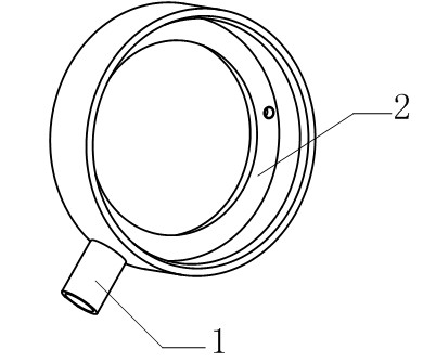
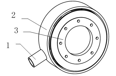
[0012] Such as Figure 1~3 The shown power distribution device for rotating targets includes a conductive rod head 1 , and its special feature is that a receiving groove 2 is provided at the top of the conductive rod head 1 used in the present invention. At the same time, an electrode carbon brush assembly is arranged in the accommodation tank 2 .

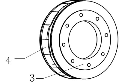
[0013] In view of a preferred embodiment of the present invention, in order to facilitate the subsequent smooth operation of the rotating target, and to meet the current stability in the power distribution process, the electrode carbon brush assembly includes an electrode ring 3, the electrode ring 3 Graphite flakes 4 are distributed on the outer circumference.

[0014] Further, through multiple comparison tests, it is found that the equidistant distribution of the graphite sheets 4 can maintain the overall power distribution effect in a relatively optimized state, which is beneficial to the operation of the target component in th...


PUM


Abstract

The invention relates to a power distribution device for a rotating target, comprising a conducting rod head. The power distribution device is characterized in that an accommodation groove is arranged at the top end of the conducting rod head; and an electrode carbon brush assembly is arranged in the accommodation groove. Therefore, the separated structure is realized and the subsequent maintenance and replacement are facilitated; meanwhile, the power distribution device can effectively meet the use requirement of a film-plating device which mainly adopts rotary driving, and can rotate smoothly.

Description

technical field [0001] The invention relates to a power distribution device, in particular to a power distribution device for a rotating target. Background technique [0002] At present, most of the equipment for producing coated glass adopts planar sputtering cathode target. Its working principle is: the glass to be coated is sent into the vacuum coating chamber, and a certain amount of high-purity process gas such as oxygen, nitrogen or Argon gas, under the action of electromagnetic field and free electrons, the process gas forms positively charged plasma. Under the attraction of the cathode carrying high negative voltage, the plasma bombards the fixed installation according to a certain trajectory and intensity under the control of the magnetic field. The coating material on the planar cathode target in the vacuum coating chamber is collided by gas molecules and deposited on the glass in a certain direction to form a film with a certain thickness. [0003] However, the e...

Claims


Application Information

Patent Timeline
IPC IPC(8): C23C14/34H01R35/00
Inventor 黄峰
Owner 黄峰
Why Eureka
Try Eureka