
Oil-gas separation device for air suction and exhaust ports of roll-cut double-side shear balance hydraulic cylinder

A technology of balancing hydraulic cylinders and separation devices, applied in the field of balancing hydraulic cylinders, which can solve problems such as oil pollution of peripheral equipment, broken balance hydraulic cylinder bases, and environmental pollution, and achieve the effects of convenient maintenance and replacement, stability and reliability, and normal operation

Active Publication Date: 2020-12-25
SD STEEL RIZHAO CO LTD
View PDF11 Cites 0 Cited by
  • Summary
  • Abstract
  • Description
  • Claims
  • Application Information

AI Technical Summary

Problems solved by technology

[0002] In the production of wide and thick plate production lines, most of the balance hydraulic cylinders used in rolling shears are single-acting cylinders. During use, the working oil in the rod cavity of the hydraulic cylinder will seep into the cylinder with the movement of the piston. After the rodless chamber, it is discharged through the oil port of the rodless chamber, and the gas with oil mist is directly discharged into the surrounding air, causing serious oil pollution of peripheral equipment and environmental pollution
In order to avoid environmental pollution, the hydraulic oil and gas are introduced into the oil barrel through the hose connected to the oil port of the hydraulic cylinder, but the oil outlet hose is blocked due to oil accumulation in the oil barrel, so that the air cannot be inhaled in time when the rodless cavity sucks air. The piston rod cannot operate normally, which in turn causes the base of the balance hydraulic cylinder to be damaged, causing serious damage to the equipment
At present, the rolling-cut double-shear balance hydraulic cylinder (single-acting cylinder) does not use oil-gas separation during the operation process, resulting in frequent failures of this equipment

Method used


Image

  • Oil-gas separation device for air suction and exhaust ports of roll-cut double-side shear balance hydraulic cylinder

Examples


Embodiment Construction

[0015] The technical solutions in the embodiments of the present invention will be described clearly and completely in further detail below in conjunction with the accompanying drawings in the embodiments of the present invention. Based on the embodiments of the present invention, all other embodiments obtained by persons of ordinary skill in the art without making creative efforts belong to the protection scope of the present invention.

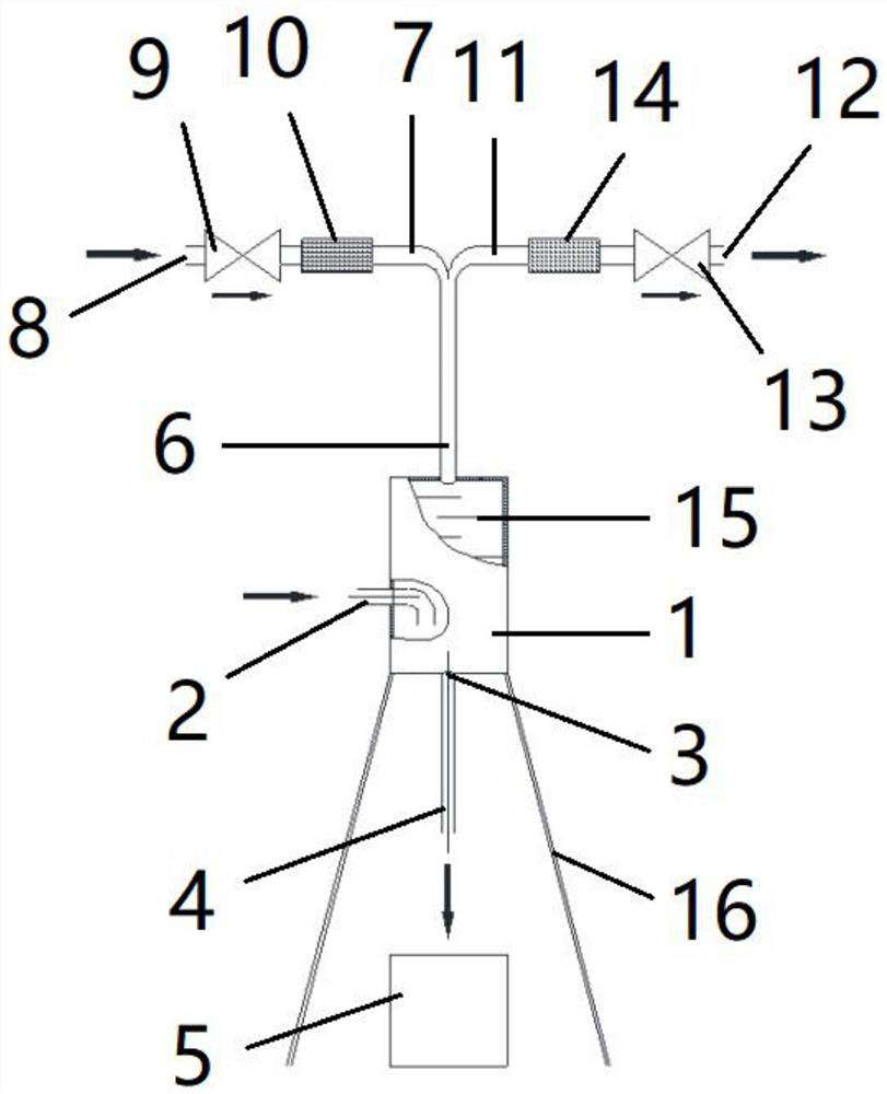
[0016] Such as figure 1 As shown, an oil-gas separation device for the suction and exhaust ports of a roll-cut double-shear balance hydraulic cylinder includes a balance hydraulic cylinder and an oil-gas separation chamber 1 connected to the suction and exhaust ports of the balance hydraulic cylinder. The balance hydraulic cylinder is a single-acting cylinder. The oil-gas separation chamber 1 is provided with staggered distribution of baffles 15, which are used to form a labyrinth structure inside the oil-gas separation chamber 1. The middle...


PUM


Abstract

The invention discloses an oil-gas separation device for air suction and exhaust ports of a roll-cut double-side shear balance hydraulic cylinder. The oil-gas separation device comprises a balance hydraulic cylinder and an oil-gas separation chamber. Baffles which are distributed in a staggered mode are arranged in the oil-gas separation chamber and used for forming a labyrinth type structure in the oil-gas separation chamber. An oil liquid discharging opening is formed in the bottom of the oil-gas separation chamber and is used for collecting oilblocked by the baffles from oil-gas mixed gas discharged to the oil-gas separation chamber by the balance hydraulic cylinder. An air inlet and outlet pipeline is installed at the top of the oil-gas separation chamber, an air inlet pipeline is connected to one side of the top end of the air inlet and outlet pipeline and used for air to enter from an air inlet through the oil-gas separation chamber when a rodless cavity of the balance hydrauliccylinder sucks air, and an air outlet pipeline is connected to the other side of the top end of the air inlet and outlet pipeline and is used for oil-gas mixed gas exhausted by the balance hydraulic cylinder to be exhausted from the oil-gas separation chamber to the exhaust port. The self-weight of oil and the exhaust and suction pressure of the balance hydraulic cylinder are used for working, normal air suction and exhaust of the balance hydraulic cylinder are guaranteed, and damage to the balance hydraulic cylinder and a support due to unsmooth air suction and exhaust in the past is avoided.

Description

technical field [0001] The invention relates to the technical field of balanced hydraulic cylinders, in particular to an oil-gas separation device for a suction and exhaust port of a roll-cut double-shear balanced hydraulic cylinder. Background technique [0002] In the production of wide and thick plate production lines, most of the balance hydraulic cylinders used in rolling shears are single-acting cylinders. During use, the working oil in the rod cavity of the hydraulic cylinder will seep into the cylinder with the movement of the piston. After the rodless chamber, it is discharged through the oil port of the rodless chamber, and the gas with oil mist is directly discharged into the surrounding air, causing serious oil pollution to the peripheral equipment and causing environmental pollution. In order to avoid environmental pollution, the hydraulic oil and gas are introduced into the oil barrel through the hose connected to the oil port of the hydraulic cylinder, but the...

Claims


Application Information

Patent Timeline
IPC IPC(8): B01D45/08
CPCB01D45/08
Inventor 张风元李嘉沛许宗国王兵杨光于彩华刘立业徐玉国徐月鑫陶丽华
Owner SD STEEL RIZHAO CO LTD
Learn More