Electrically operated valve and heat exchange device comprising same

A technology of electric valve and valve needle, which is applied in the direction of valve operation/release device, valve device, valve details, etc., which can solve the problems of increasing manufacturing cost, increasing coaxiality error, eccentric wear, etc., and avoiding eccentric wear Problems, reduction of coaxiality error, effect of reduction of frictional resistance

Inactive Publication Date: 2011-11-23
ZHEJIANG SANHUA INTELLIGENT CONTROLS CO LTD
View PDF7 Cites 16 Cited by
  • Summary
  • Abstract
  • Description
  • Claims
  • Application Information

AI Technical Summary

Problems solved by technology

[0006] In the above-mentioned prior art, the guide sleeve 4' is bent at the lower part and connected with the stretched valve seat 9'. Since the forming precision of the stretched valve seat 9' is not high, the valve port 1'1 of the valve core seat 1' is connected with the stretched valve seat 9'. There is an assembly coaxiality error between the stretched valve seat 9', which in turn leads to a large coaxiality error between the valve port 1'1 and the guide sleeve 4'
In addition, the bending structure of the lower end of the guide sleeve 4' is relatively complicated, and the machining accuracy is difficult to guarantee. On the one hand, the manufacturing cost is increased, and on the other hand, the distance between the guide sleeve 4' and the valve port 1'1 is also increased. Concentricity error
[0007] There is a large coaxiality error between the guide sleeve 4' and the valve port 1'1, which will lead to a large coaxiality error between the valve needle 2' and the valve port 1'1, which will cause the valve port 1' 1 Problems such as poor sealing and eccentric wear
In addition, there is a large coaxiality error between the guide sleeve 4' and the valve port 1'1, which will also increase the frictional resistance when the rotor 6' rotates, thereby affecting the reliability of the electric valve.

Method used


Image

  • Electrically operated valve and heat exchange device comprising same
  • Electrically operated valve and heat exchange device comprising same
  • Electrically operated valve and heat exchange device comprising same

Examples


Embodiment Construction

[0026] The core of the present invention is to provide an electric valve, which can improve the coaxiality between the guide sleeve and the valve port, thereby improving the sealing performance between the valve needle and the valve port on the one hand, and reducing the Frictional resistance when the rotor turns. In addition, another core of the present invention is to provide a heat exchange device including the above electric valve.

[0027] In order to enable those skilled in the art to better understand the technical solutions of the present invention, the present invention will be further described in detail below in conjunction with the accompanying drawings and specific embodiments.

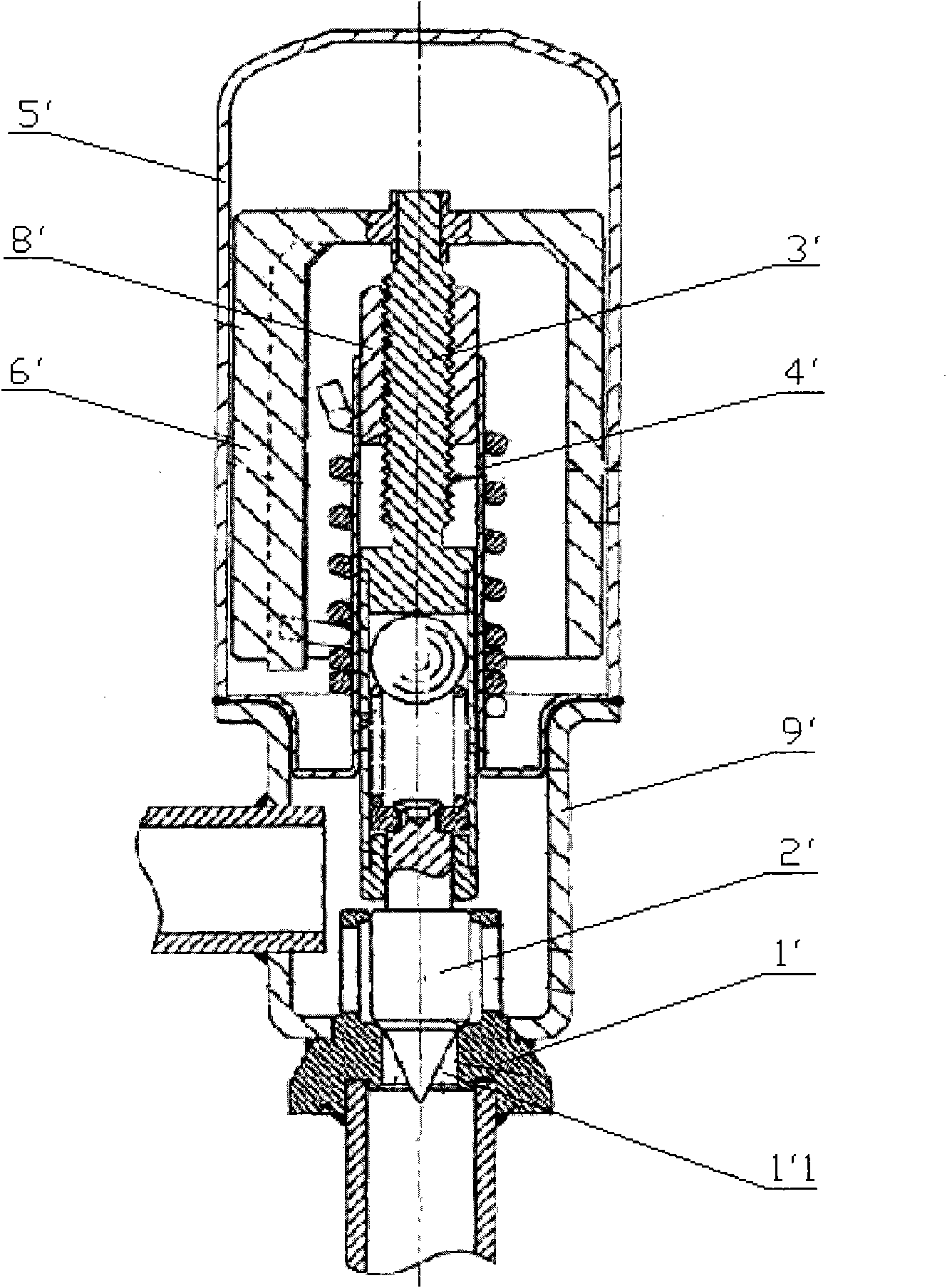
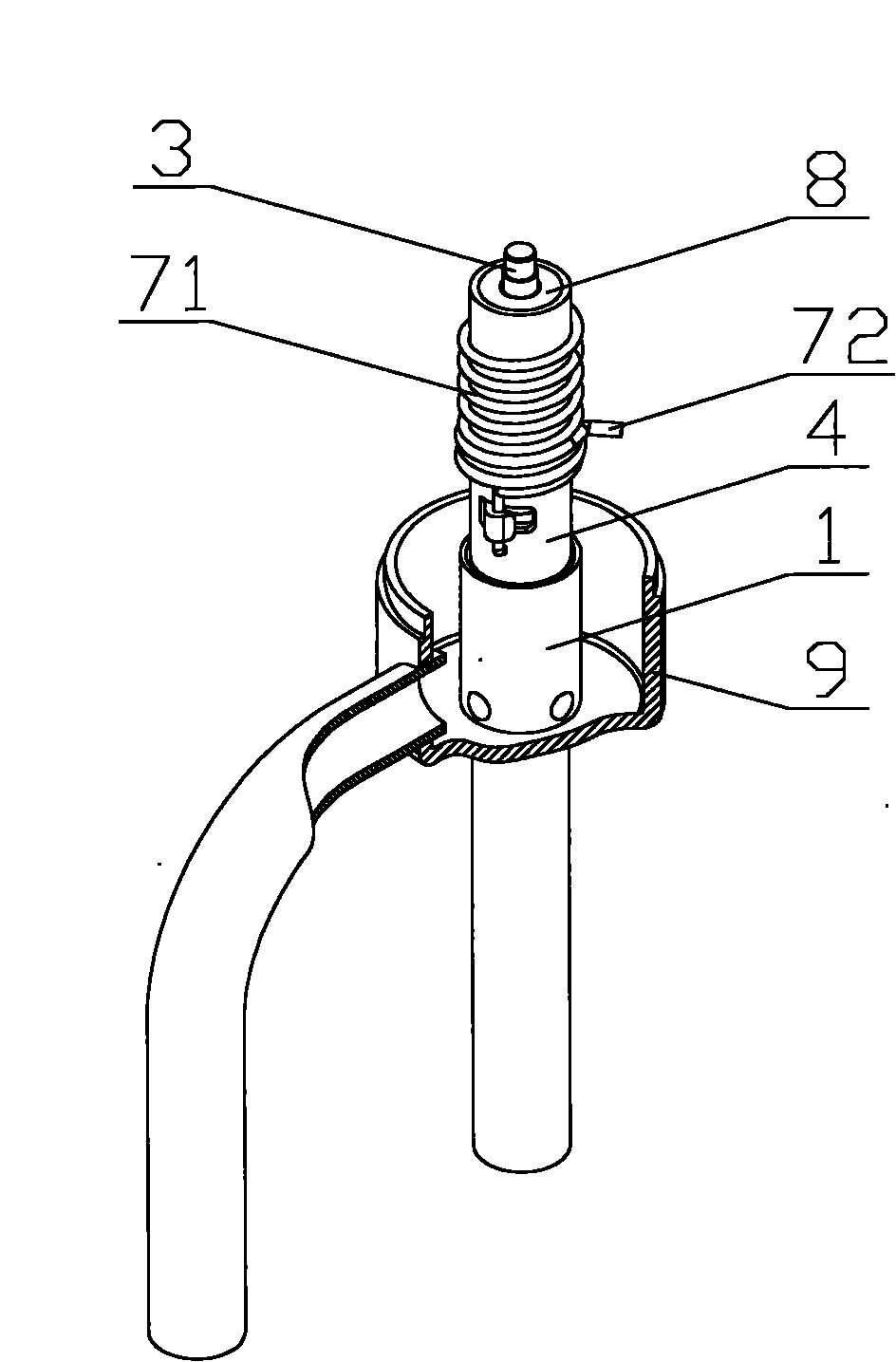
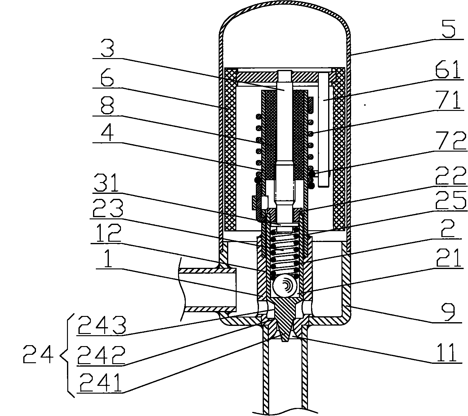
[0028] Please refer to figure 2 , image 3 and Figure 4 , figure 2 It is an axonometric schematic diagram of an electric valve in an embodiment of the present invention; image 3 for figure 2 Front sectional view of the electric valve; Figure 4 It is a front sectional view of ...


PUM


Abstract

The invention discloses an electrically operated valve. The electrically operated valve comprises a valve plug base (1) which is provided with a valve plug cavity and a valve port (11) communicated with the valve plug cavity, and a valve needle (2) which is extended into the valve plug cavity and is matched with the valve port (11); a lead screw (3) is connected with the upper part of the valve needle (2); and a pilot sleeve (4) is arranged outside the lead screw (3) and is fixedly connected with the valve plug base (1). By the electrically operated valve, the concentricity between the pilot sleeve (4) and the valve port (11) can be improved so that the sealing performance between the valve needle (2) and the valve port (11) can be improved and the frictional resistance during rotation of a rotator (6) can be reduced. Moreover, the invention also discloses a heat exchange device comprising the electrically operated valve.

Description

technical field [0001] The invention relates to the technical field of flow control components, in particular to an electric valve. In addition, the present invention also relates to a heat exchange device comprising the above electric valve. Background technique [0002] In the field of refrigeration technology, the electric valve is the refrigerant flow control part of the refrigeration equipment. Its working process is generally: the electric valve is opened or closed in the refrigeration equipment system such as air conditioners, so as to control the circulation and interruption of the refrigerant, and can also adjust the flow of the refrigerant. size. Of course, the scope of application of the electric valve is not limited to the above-mentioned refrigeration technology field, for example, it is also widely used in the hydraulic field. [0003] Please refer to figure 1 , figure 1 It is a structural schematic diagram of a typical electric valve in the prior art. [...

Claims


Application Information

Patent Timeline
Patent Type & Authority Applications(China)
IPC IPC(8): F16K27/02F16K31/02
Inventor 魏先让
Owner ZHEJIANG SANHUA INTELLIGENT CONTROLS CO LTD
Why Eureka
Try Eureka