Tightening device communicated with multiple osmometers

A technology of fastening device and osmometer, applied in measuring device, using stable tension/pressure test material strength, instrument and other directions, can solve the problems of low work efficiency, large compression ratio, difficult exhaust, etc. The effect of working efficiency, preventing oil leakage and reducing errors

Active Publication Date: 2011-11-23
SINOHYDRO BUREAU 7 CO LTD
View PDF6 Cites 0 Cited by
  • Summary
  • Abstract
  • Description
  • Claims
  • Application Information

AI Technical Summary

Problems solved by technology

[0004] 2. The existing fastening device is difficult to exhaust, and the error is large: because the connection between the fastening device and the pressurization equipment uses a long transparent tube, it needs to be lifted high when exhausting, and the exhaust residual volume is difficult to control, which may easily cause the gas content to exceed standard
The compression ratio of gas is larger than that of oil, resulting in large errors and inaccurate detection readings
[0005] 3. The existing fastening device can only clamp one piezometer at a time, and the work efficiency is low

Method used


Image

  • Tightening device communicated with multiple osmometers
  • Tightening device communicated with multiple osmometers
  • Tightening device communicated with multiple osmometers

Examples


Embodiment Construction

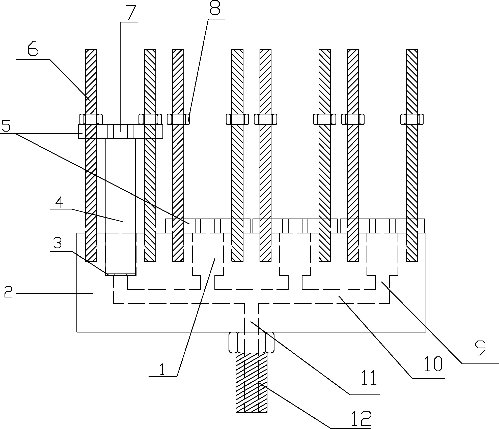
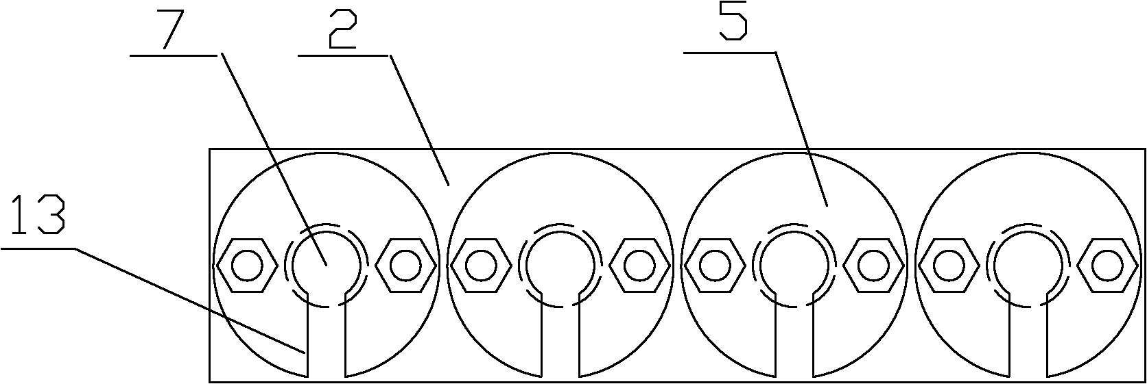
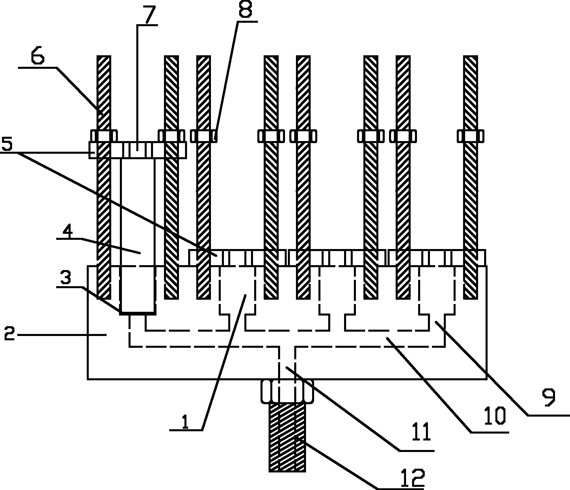
[0015] See figure 1 , figure 2 , The present invention has a base 2, on which a piezometer hole 1 is opened, the lower part of the base 2 is connected with a pressure device, and the pressure device has a pressure pipe 11 leading into the piezometer hole 1. The key technology is that there is more than one piezometer hole 1 on the base 2, a polyurethane gasket 3 is provided at the bottom of the piezometer hole 1, and a hole is provided in the middle of the polyurethane gasket 3 to pressurize the piezometer. A pressurized pipe 11 is opened in the base 2, and the pressurized pipe 11 is connected to a connecting pipe 10. On the connecting pipe 10, there are branch pipes 9 which respectively lead to each piezometer hole 1. A cover plate 5 is provided above the piezometer hole 1. In the middle of the cover plate 5, there is an orifice 7 corresponding to the piezometer hole 1. On both sides of the orifice 7, there are screw holes, and the base 2 is located on both sides of the piezo...


PUM


Abstract

The invention relates to a tightening device communicated with multiple osmometers, and the device is mainly applied in the mechanical property inspection technology of a monitoring instrument of vibrating wire osmometer. The device has a pedestal which is provided with hole sites of osmometers, and the bottom of the pedestal is connected to a pressure device, the pressure pipeline of which is introduced into the osmometer hole sites. The key technique lies in that: more than one osmometer hole site is installed on the pedestal, within which the pressure pipeline is located, and the pressure pipeline is connected to a communicating pipe which is equipped with branch pipes introduced into each osmometer hole site; a cover plate is mounted over the osmometer hole sites, and the central section of the cover plate is provided with orifices corresponding to the osmometer hole sites, and two sides of the orifices are equipped with upper screw holes, while lower screw holes corresponding to the upper screw holes are disposed at two sides of the osmometer hole sites on the pedestal, and tightening screws with nuts are placed into the upper and lower screw holes. With a pedestal of multiple communicated osmometer hole sites, the device of the invention can detect multiple osmometers successfully at one time, so that the working efficiency is greatly improved, and the placement of osmometers is simplified, thus saving time and labor.

Description

Technical field: [0001] The fastening device of the connected multi-element piezometer is mainly used in the fastening device of the vibrating wire piezometer mechanical performance inspection technology of the monitoring instrument. Background technique: [0002] The existing fastening device used in the inspection technology of the vibrating wire piezometer for monitoring instruments has a base. The base is provided with holes for the piezometer. The lower part of the base is connected with a pressure device. The following defects need to be overcome: [0003] 1. There are two annular rubber waist rings in the middle and upper part. The piezometer must pass through these two barriers to enter the piezometer hole. The wall thickness of the piezometer tube is only 1-2mm thick, which is very sharp. In the process of pressing the piezometer, it must be completely vertical, otherwise the rubber ring will be cut on the side and it is difficult to detect when it is slightly tilted. Only...

Claims


Application Information

Patent Timeline
IPC IPC(8): G01N3/02G01N3/12
Inventor 王华帅永建
Owner SINOHYDRO BUREAU 7 CO LTD
Why Eureka
Try Eureka