Main circuit for increasing power factor of controllable silicon power supply

A technology of power supply and thyristor, which is used in high-efficiency power electronic conversion, output power conversion devices, electrical components, etc. problem, to achieve the effect of high power factor and small pollution

Inactive Publication Date: 2014-04-23
国充充电科技江苏股份有限公司 +1
View PDF3 Cites 0 Cited by
  • Summary
  • Abstract
  • Description
  • Claims
  • Application Information

AI Technical Summary

Problems solved by technology

[0004] However, the problem existing in the main circuit of the traditional thyristor power supply is: when the output voltage of the thyristor power supply is high and the output current is large, the conduction angle of the thyristor SCR1~SCR6 is relatively large.
In order to meet the large current output by the power supply, at this time, because the conduction time of the thyristor in the half cycle of the power grid is relatively short, the peak value of the current flowing through the thyristor must be very high. Therefore, the harmonic current caused by the grid side It is also relatively large, and the pollution to the power grid is also relatively large.
Since the conduction angle of the thyristor is small (for example, about 30 degrees), the phase difference between the voltage and current of the power grid is also large, and the power factor of the power supply is also low at this time.

Method used


Image

  • Main circuit for increasing power factor of controllable silicon power supply
  • Main circuit for increasing power factor of controllable silicon power supply
  • Main circuit for increasing power factor of controllable silicon power supply

Examples


Embodiment Construction

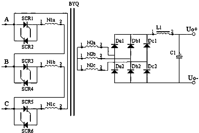
[0017] Such as Figure 4 As shown, the circuit composition of transformer primary winding, thyristor, three-phase power frequency voltage and so on is the same as figure 1 Exactly the same: the anode of the thyristor SCR1, the cathode of SCR2 are connected to the A phase of the three-phase power frequency voltage and the two ends of the primary winding N1c of the transformer, the cathode of the thyristor SCR1, the anode of SCR2 are connected to the first phase of the winding N1a Connection; the anode of the thyristor SCR3, the cathode of SCR4 are connected to the B phase of the three-phase power frequency voltage and the two ends of the primary winding N1a, the cathode of the thyristor SCR3, the anode of SCR4 are connected to the first end of the primary winding N1b ; The anode of the thyristor SCR5, the cathode of SCR6 are connected to the C phase of the three-phase power frequency voltage and the two ends of the primary winding N1b, the cathode of the thyristor SCR5, the ano...


PUM


Abstract

The invention discloses a main circuit for increasing the power factor of a controllable silicon power supply, which relates to the technical field of high-power controllable silicon power supplies and transformers thereof. The main circuit is characterized in that: a transformer is provided with at least two groups of secondary windings, wherein each group of secondary windings constitutes a basic low-voltage power supply together with a three-phase full-wave rectifier bridge, an inductor, a capacitor, an electronic switch and a diversion diode; and the diversion diode in the basic low-voltage power supply is reversely connected to an output positive terminal and an output negative terminal of the basic low-voltage power supply. When the power supply is continuously adjustable, primary controllable silicon of the transformer can keep a larger conduction angle, which is generally about 120 degrees, so that a higher power factor of a power grid can be always kept, a lower peak value of resonant current is kept, and small pollution to the power grid is kept.

Description

technical field [0001] The invention relates to the technical field of a high-power thyristor power supply and a transformer thereof. Background technique [0002] The main circuit of the traditional thyristor power supply includes three pairs of thyristors connected to the three-phase power frequency voltage and three sets of primary windings, and the three sets of secondary windings are connected to a three-phase full-wave rectifier bridge, the three-phase full-wave rectifier After the positive output of the bridge is connected in series with an inductor, it is connected with the positive terminal of a capacitor and the positive output terminal of the power supply. The output negative pole of the three-phase full-wave rectifier bridge and the negative pole of the capacitor are connected to the negative output terminal of the power supply. The specific main circuit schematic diagram is as follows: figure 1 Shown: the anode of the thyristor SCR1, the cathode of SCR2 are co...

Claims


Application Information

Patent Timeline
Patent Type & Authority Patents(China)
IPC IPC(8): H02M1/42
CPCY02B70/126Y02B70/10Y02P80/10
Inventor 杨君宽魏栋梁曹祖国
Owner 国充充电科技江苏股份有限公司
Why Eureka
Try Eureka