Audio signal receiving device and audio signal transmission system

An audio signal receiving and audio signal technology, applied in the electronic field, can solve problems such as inability to communicate, and achieve the effect of reducing cost and volume

Active Publication Date: 2013-06-26
TENDYRON CORP
View PDF6 Cites 0 Cited by
  • Summary
  • Abstract
  • Description
  • Claims
  • Application Information

AI Technical Summary

Problems solved by technology

[0004] The speaker interface to USB interface adapter cable in the prior art (for example, a 3.5mm headphone jack to USB interface adapter cable) can only be connected with a USB host device (for example, a personal computer) and a speaker interface device (for example, a mobile communication device) , for normal communication between the speaker interface device (e.g., a mobile communication device) and the USB host device
And the existing electronic equipment that is provided with USB interface usually belongs to USB slave equipment, can't use the horn interface in the prior art to transfer the USB interface adapter line and carry out communication with mobile communication device

Method used


Image

  • Audio signal receiving device and audio signal transmission system
  • Audio signal receiving device and audio signal transmission system
  • Audio signal receiving device and audio signal transmission system

Examples


no. 1 example

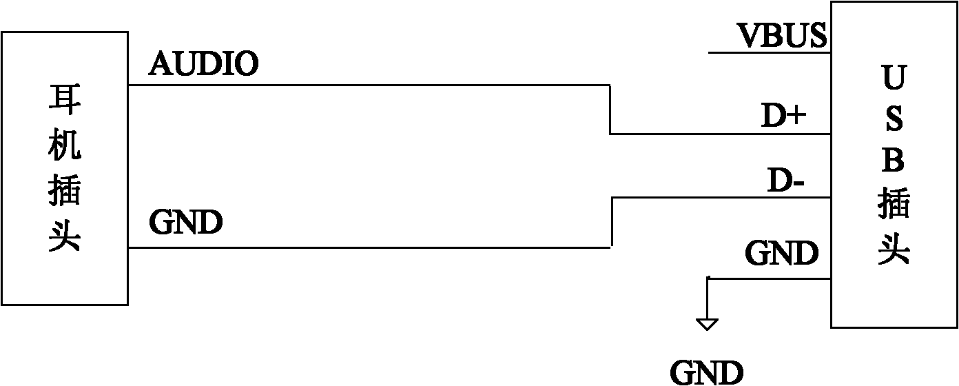
[0045] figure 1 It is a schematic structural diagram of the first embodiment of the audio signal switching device of the present invention; figure 1 As shown, the audio signal conversion device includes: a speaker interface (such as a telephone handset interface or figure 1 headphone plug shown), adapter port (such as figure 1 USB plug shown); where:

[0046] The earphone plug is used to connect with the earphone jack of the audio signal sending device (for example, mobile phone) to receive the audio signal output by the audio signal sending device.

[0047] Included in the headphone plug are: audio pins (such as figure 1 AUDIO pin shown), ground pin.

[0048] The USB plug is used to connect with the USB slot of the audio signal receiving device to output the audio signal thereto.

[0049] The USB plug includes: power pin (VBUS pin), D+ pin, D- pin, and ground pin.

[0050] In this embodiment, the audio pin of the earphone plug is connected to the D+ pin of the USB plug,...

no. 2 example

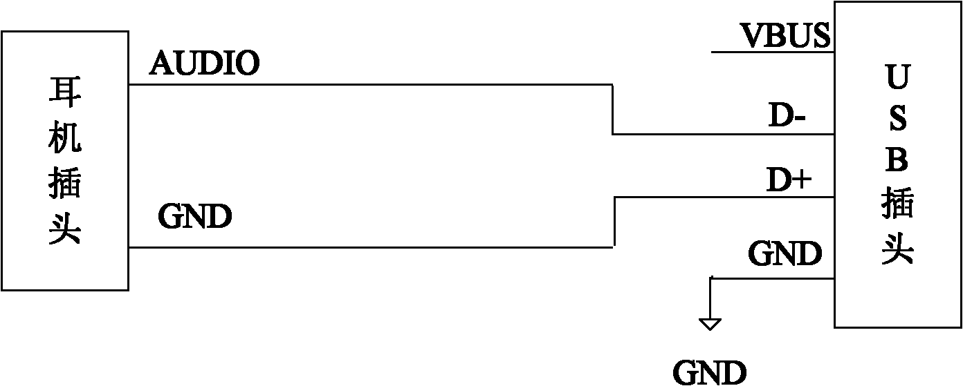
[0064] image 3 It is a schematic structural diagram of the second embodiment of the audio signal switching device of the present invention; image 3 As shown, the difference between the second embodiment of the audio signal switching device of the present invention and the first embodiment is:

[0065] In the second embodiment, the audio signal conversion device connects the D- pin of the USB plug as an audio signal pin to the audio pin of the earphone plug, and uses the D+ pin as a reference signal pin to connect to the ground pin of the earphone plug. Connected to output audio signal to audio signal receiving device.

[0066] The second embodiment of the audio signal receiving device is the same as the first embodiment.

[0067] The second embodiment of the audio signal transmission system of the present invention is composed of the above audio signal switching device and audio signal receiving device.

no. 3 example

[0069] The third embodiment of the audio signal switching device of the present invention is the same as the first embodiment.

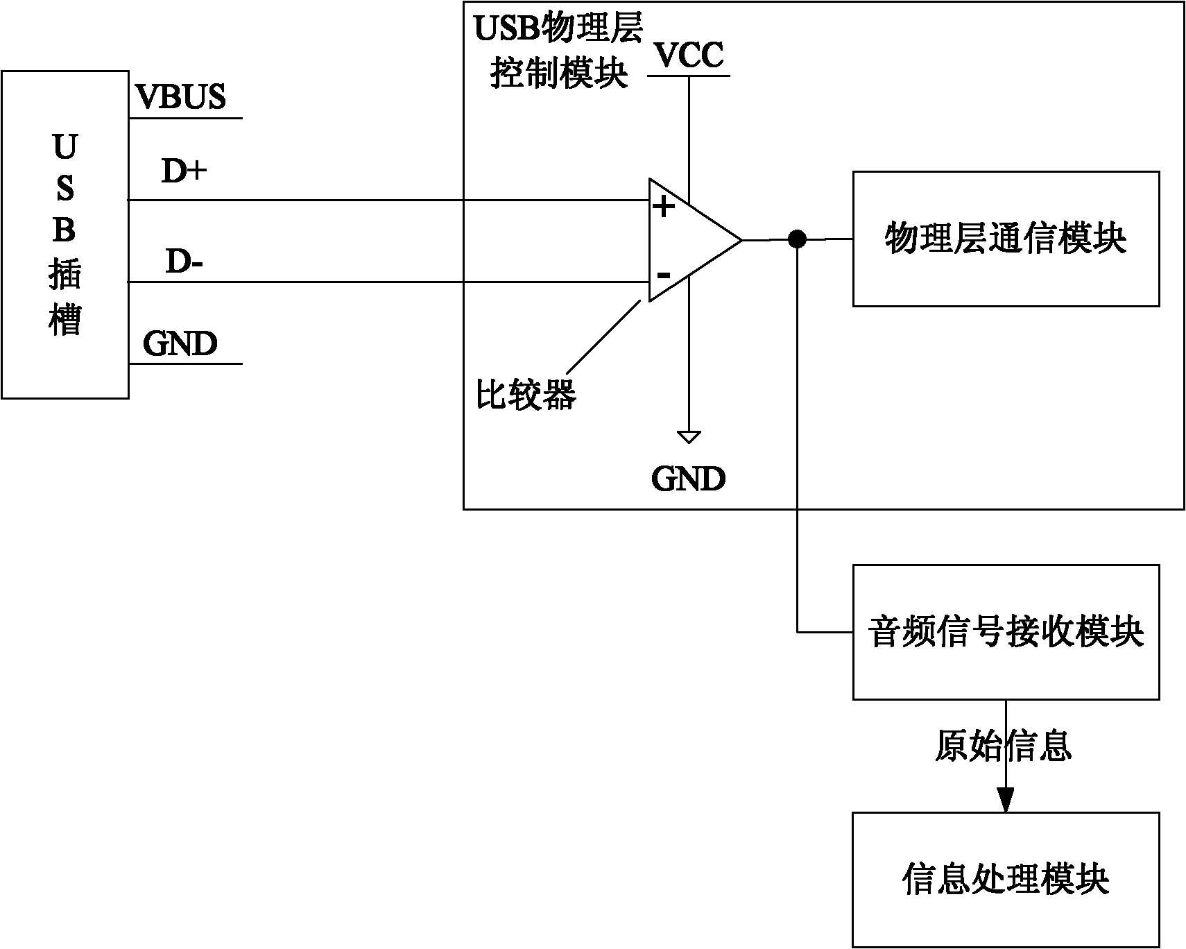
[0070] Figure 4 It is a schematic structural diagram of the fourth embodiment of the audio signal receiving device of the present invention; Figure 4 As shown, the difference between the third embodiment of the audio signal receiving device and the first embodiment is:

[0071] In the third embodiment, the audio signal receiving module is arranged in the USB physical layer control module, the audio signal receiving module is connected with the output pin of the comparator of the USB physical layer control module, and receives the audio signal through the output pin of the comparator The corresponding square wave (i.e. data in binary form).

[0072] According to different system requirements, the audio signal receiving module can also decode the binary data to obtain its corresponding original information (for example, the challenge code used to g...


PUM


Abstract

An audio signal receiving device and an audio signal transmission system, the system includes: an audio signal transfer device, an audio signal receiving device; the audio signal transfer device includes: an audio interface, a transfer port interface; the audio pin of the audio interface and the The audio signal pins of the adapter interface are connected, and the ground wire pins of the audio interface are connected with the reference signal pins of the adapter interface; the audio signal receiving device includes: the receiver interface, the USB physical layer control module, the audio signal receiving Module; the receiver interface includes: audio signal pins, reference signal pins; the USB physical layer control module includes a comparator, the positive and negative poles of the comparator are connected to the audio signal pins and reference signal pins of the receiver interface; audio The signal receiving module is connected with the output pin of the comparator, and receives the square wave corresponding to the audio signal through the output pin of the comparator.

Description

technical field [0001] The invention relates to the field of electronic technology, in particular to an audio signal receiving device and an audio signal transmission system. Background technique [0002] With the development of audio signal encoding / decoding technology, more and more electronic devices transmit data through audio interface. For example, the electronic device may be connected to the mobile communication device through a speaker interface (eg, earphone interface) of the mobile communication device (eg, a mobile phone), and receive audio signals output by the mobile communication device. [0003] In addition, with the popularization of USB interfaces, a large number of electronic devices are provided with USB interfaces, so how to transmit audio signals between mobile communication devices and electronic devices through the speaker interface of the mobile communication device and the USB interface of the electronic device is a current need. Solved technical p...

Claims


Application Information

Patent Timeline
Patent Type & Authority Patents(China)
IPC IPC(8): H04R3/00
CPCG06F3/162H01R31/065H04M1/6058G06F13/385
Inventor 李东声
Owner TENDYRON CORP
Why Eureka
Try Eureka