
Eureka
For R&D, Eureka makes reading and utilizing patents & technical documents easy.
Eureka AIR
Designed for self-driven R&D workflows. Generate viable solutions, solve complex R&D challenges, empower your innovation with AI.

Eureka Materials
Designed for material experts only. Revolutionize your material R&D, from search, analyze, to developing new materials.

TechResearch
Generate reliable direction feasibility study reports for your R&D in just a few steps.

TechSeek
Discover and master advanced knowledge NOW. Basics, ideas, possibilities, all at once.

TechMind
As an expert in R&D Theories, TechMind can generates customized viable solutions instantly.

TechRisk
Analyze your overall solution with one click, know your potential R&D risks in advance.

TechMonitor
Get weekly tech updates, stay abreast of the latest tech innovations and key insights.
Speaker unit, manufacturing method therefor and portable information terminal
A manufacturing method and a loudspeaker technology, which are applied to sensors, electrical components, circuit lead arrangement/elimination, etc., can solve problems such as disconnection of the wiring part, and achieve the effect of preventing the disconnection of the wiring part and preventing disconnection
- Summary
- Abstract
- Description
- Claims
- Application Information
AI Technical Summary
Problems solved by technology
Method used
Image

Examples
Embodiment approach 1
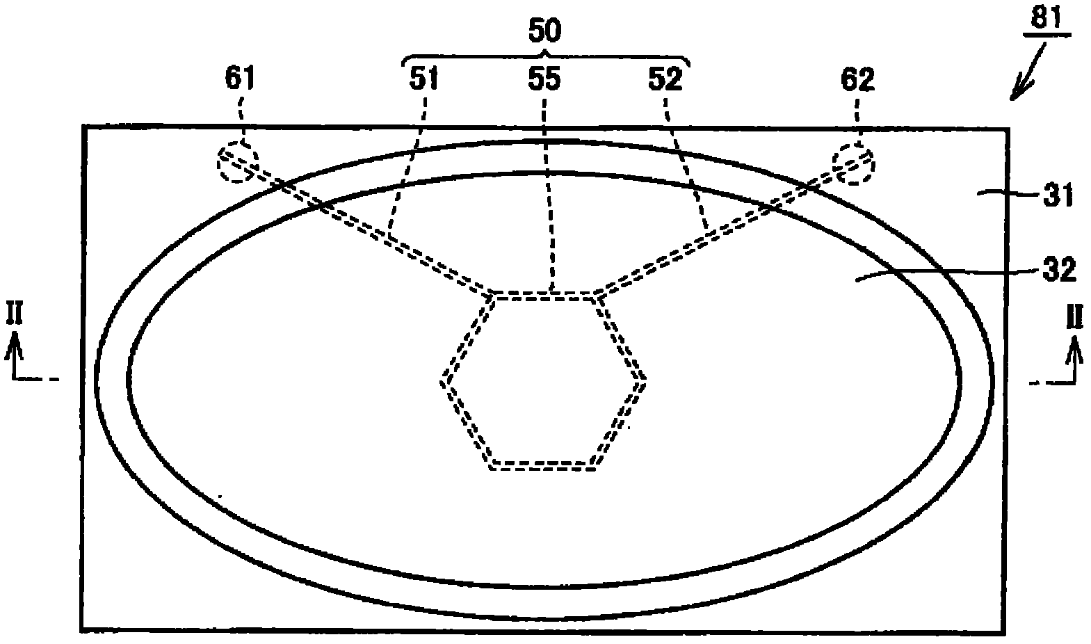
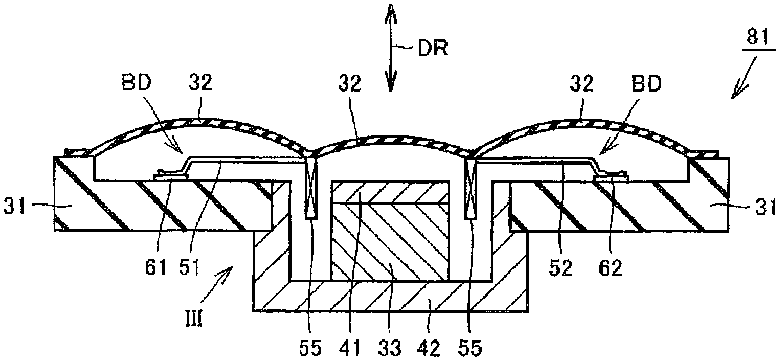
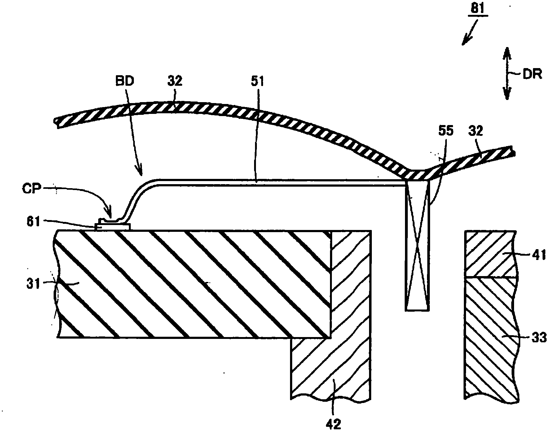
[0018] figure 1 It is a plan view schematically showing the structure of the speaker unit according to Embodiment 1 of the present invention. also, figure 2 is along figure 1 A brief cross-sectional view of line II-II. in addition, image 3 yes figure 2 Brief magnification near arrow III of .
[0019] refer to Figure 1 ~ Figure 3 , The speaker unit 81 of this embodiment has a frame 31 , a diaphragm 32 , a magnet 33 , a pole piece 41 , a yoke 42 , and a voice coil 50 .
[0020] The frame 31 has a pair of terminals 61 , 62 . The vibrating piece 32 is supported by the frame 31 so as to be able to vibrate in the vibration direction DR (one direction). The terminals 61 and 62 each have a surface for connecting wiring, and the surface is perpendicular to the vibration direction DR.
[0021] The magnet 33 is arranged on the yoke 42 . Also, the yoke 42 is attached to the frame 31 . According to this configuration, the magnet 33 is fixed to the frame 31 via the yoke 42 . ...
Embodiment approach 2
[0052] Figure 20 It is a plan view schematically showing the structure of the speaker unit according to Embodiment 2 of the present invention. also, Figure 21 is through Figure 20 The viewpoint of the blank arrow schematically represents a partial side view of the structure of the voice coil.
[0053] refer to Figure 20 and Figure 21 The speaker unit 81v of the present embodiment includes a voice coil 50v instead of the voice coil 50 in the first embodiment. The voice coil 50v has wiring parts 51v and 52v. The wiring portions 51v and 52v are respectively drawn from one vertex of the polygonal shape of the winding portion 55 . The wiring parts 51v and 52v are pulled out from the winding part 55 so that there is no sharp bend in the wiring between the wiring part 51v and the winding part 55 and between the wiring part 52v and the winding part 55. around the direction to become co-winding.
[0054] Next, a method of mounting the voice coil 50v in the method of manufa...
Embodiment approach 3
[0063] Figure 23 It is a partial perspective view schematically showing the structure of the operation surface side of the portable information terminal according to Embodiment 3 of the present invention. also, Figure 24 is a schematic representation Figure 23 A partial perspective view of the structure of the back side of the portable information terminal.
[0064] refer to Figure 23 and Figure 24 , the portable information terminal of the present embodiment is a portable telephone, has an upper frame body 101, a display portion 102, a sound outlet 103, a hinge portion 104, a lower frame body 105, an operation button 106, a number button 107, and a display portion 111 , sound hole 112, a plurality of speaker units 81 (in Figure 23 and Figure 24 not shown).
[0065] A speaker unit 81 is built in the vicinity of the sound outlet 103 as a receiver for generating received sound or the like. In addition, another speaker 81 is built in the vicinity of the sound hole ...
PUM
 Abstract
Description
Claims
Application Information
 - R&D Engineer
- R&D Manager
- IP Professional
- Industry Leading Data Capabilities
- Powerful AI technology
- Patent DNA Extraction
Browse by: Latest US Patents, China's latest patents, Technical Efficacy Thesaurus, Application Domain, Technology Topic, Popular Technical Reports.
© 2024 PatSnap. All rights reserved.Legal|Privacy policy|Modern Slavery Act Transparency Statement|Sitemap|About US| Contact US: help@patsnap.com