Medical anoscope

An anoscope and an examination mirror technology, applied in the field of medical anoscope, can solve the problems of inconvenient fixing of an examination lens tube, inconvenience to carry and normal use, relative movement of components, etc., and achieve the effects of convenient fixing, low manufacturing cost, and convenient pulling

Inactive Publication Date: 2011-11-30
迟伟林
View PDF4 Cites 2 Cited by
  • Summary
  • Abstract
  • Description
  • Claims
  • Application Information

AI Technical Summary

Problems solved by technology

[0002] Existing anoscopes can be divided into straight handle type and horizontal handle type according to the different handle forms. However, although the straight handle type medical anoscope is convenient for medical staff to push the mirror body into the anus, it is inconvenient to pull the anoscope body. The inspection lens barrel is fixed when the mirror core is used, which affects the inspection accuracy; although the horizontal handle medical anoscope is convenient to fix the inspection lens barrel when pulling the mirror core, it is inconvenient to apply force to the mirror body to push the medical anoscope into the anus
In addition, the existing anoscope has a relatively loose structure, and during the process of carrying and using, each part is prone to relative movement, which is not convenient for carrying and normal use

Method used


Image

  • Medical anoscope
  • Medical anoscope
  • Medical anoscope

Examples


Embodiment Construction

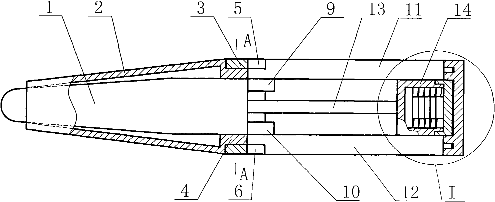
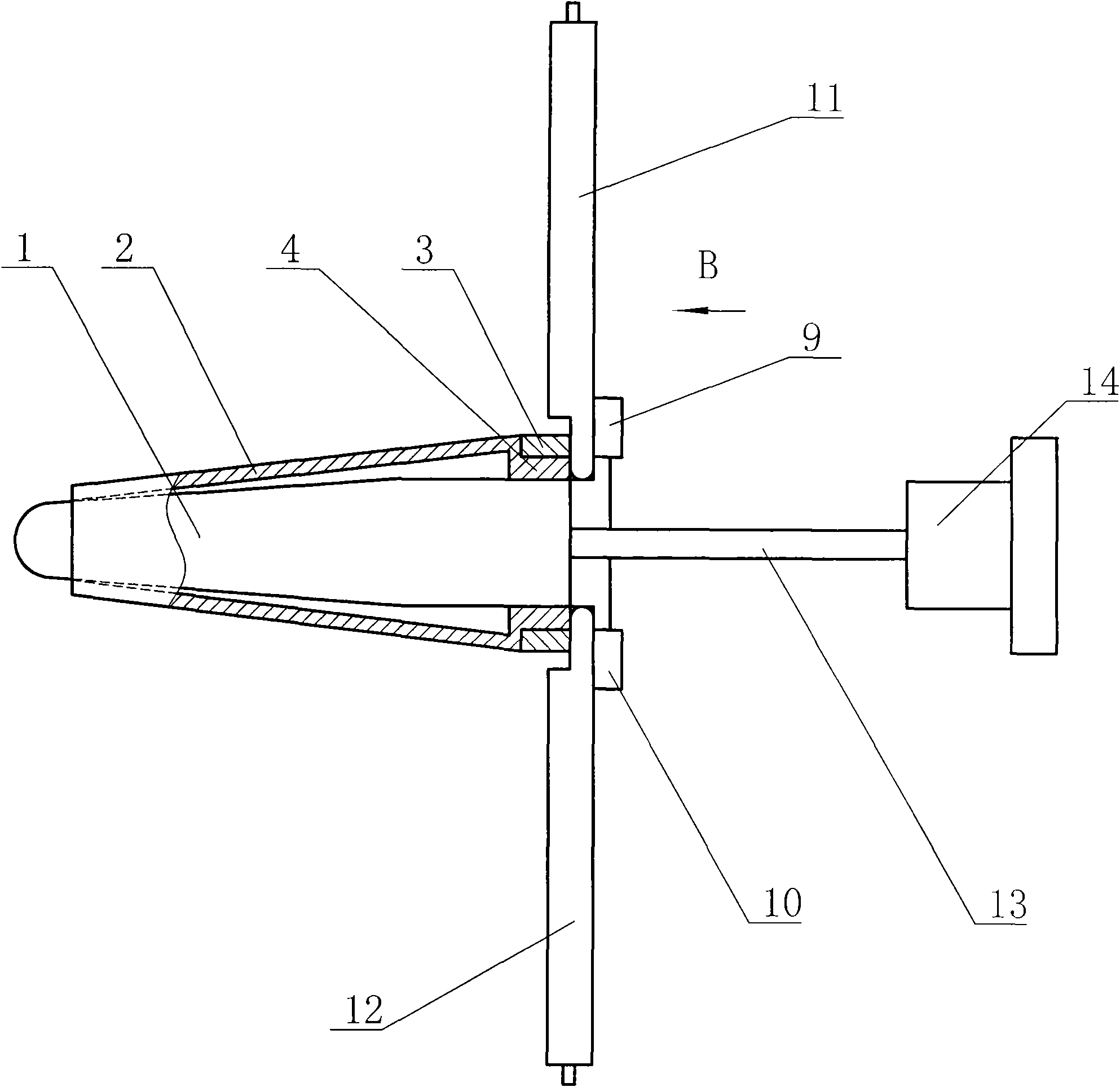
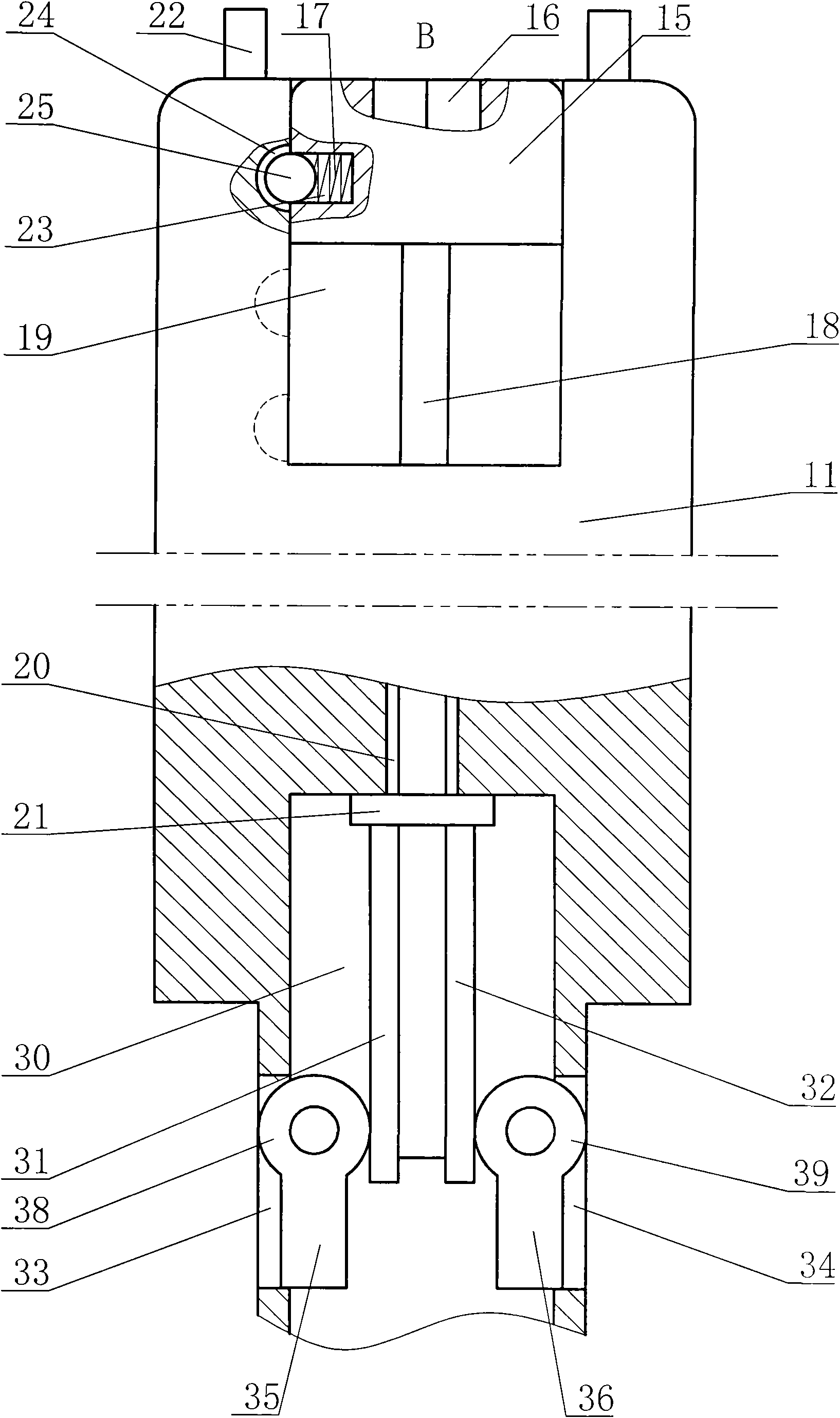
[0009] The medical anoscope of the present invention comprises an inspection lens barrel 2, the inspection lens barrel 2 is a progressively expanding tube with a small front end and a large rear end, and a mirror core 1 is installed in the inspection lens barrel 2, and the front end of the mirror core 1 is a ball head, and the ball The head is located outside the inspection lens barrel 2, and the rear end of the inspection lens barrel 2 is provided with a connecting sleeve 4, and the outer circumference of the connecting sleeve 4 is movable to install a locking ring 3, and the locking ring 3 can rotate relative to the connecting sleeve 4. The length of the locking ring 3 is greater than that of the connecting sleeve 4, so that when the first handle 11 and the second handle 12 are unfolded, they can snap into the locking ring 3 for positioning. Such as figure 1 As shown, the first handle 11 and the second handle 12 are symmetrically installed on the connecting sleeve 4 with the...


PUM


Abstract

The invention discloses a medical anoscope. The medical anoscope comprises an examination anoscope barrel, wherein an anoscope core is arranged in the examination anoscope barrel, a pull rod is arranged at the rear end of the anoscope core, a connecting sleeve is arranged at the rear end of the examination anoscope barrel, a locking ring and two handles are arranged on the connecting sleeve, and front ends of the two handles are hinged with the connecting sleeve respectively; the locking ring is provided with two positioning grooves, and the connecting sleeve is provided with positioning blocks; the first handle is provided with a first mounting cavity, a nut and a connecting rod are arranged in the first mounting cavity, and a second mounting cavity and a connecting rod groove are formedin the first handle; a limiting boss is arranged in the second mounting cavity and provided with two racks; the front end of the connecting rod is connected with the limiting boss; the side wall of the first handle is provided with two swinging block grooves, two gears are arranged in the second mounting cavity, the gears and the racks are engaged, and the two gears are movably connected with thehandles and are provided with swinging blocks; and the side wall of the nut is provided with a mounting hole, a spring and a steel ball are arranged in the mounting hole, and the side wall of the first mounting cavity is provided with three positioning round holes.

Description

technical field [0001] The invention relates to a medical device, specifically a medical anoscope. Background technique [0002] Existing anoscopes can be divided into straight handle type and horizontal handle type according to the different handle forms. However, although the straight handle type medical anoscope is convenient for medical staff to push the mirror body into the anus, it is inconvenient to pull the anoscope body. When the lens core is fixed, the inspection lens barrel is fixed, which affects the inspection accuracy; while the horizontal handle medical anoscope is convenient to fix the inspection lens barrel when the lens core is pulled, but it is inconvenient to apply force to the lens body to push the medical anoscope into the anus. In addition, the existing anoscope has a relatively loose structure, and during the process of carrying and using, various parts tend to move relative to each other, making it inconvenient to carry and use normally. Contents o...

Claims


Application Information

Patent Timeline
Patent Type & Authority Applications(China)
IPC IPC(8): A61B1/31
Inventor 迟伟林
Owner 迟伟林
Why Eureka
Try Eureka