
Digital-control oil and water pressurizing measuring tank

A metering box, oil-water technology, applied in the field of oil transfer stations, can solve the problems of large floor space, long construction period, poor adaptability, etc., and achieve the effect of small floor space, fewer operators, and short construction period

Inactive Publication Date: 2013-01-02
鲍云波 +1
View PDF4 Cites 0 Cited by
  • Summary
  • Abstract
  • Description
  • Claims
  • Application Information

AI Technical Summary

Problems solved by technology

[0003] The purpose of the present invention is to provide a digitally controlled oil-water pressurized metering box to solve the problems of large floor area, many production and operation operators, poor safety, long construction period and poor adaptability in existing oil transfer stations

Method used


Image

  • Digital-control oil and water pressurizing measuring tank
  • Digital-control oil and water pressurizing measuring tank
  • Digital-control oil and water pressurizing measuring tank

Examples


specific Embodiment approach 1

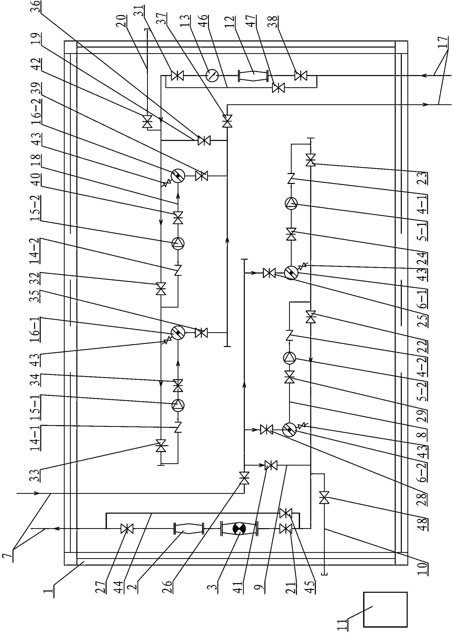
[0008] Specific implementation mode one: combine figure 1 Describe this embodiment. This embodiment includes a box body 1, a first flow stabilizer 2, an oil flow meter 3, a first check valve 4-1, a second check valve 4-2, and a first oil delivery pump 5- 1. The second oil delivery pump 5-2, the first filter 6-1, the second filter 6-2, the oil pipe 7, the first connecting pipe 8, the second connecting pipe 9, the digital frequency conversion equipment 11, the second flow stabilizer 12 , water mixed flowmeter 13, the third one-way valve 14-1, the fourth one-way valve 14-2, the first water delivery pump 15-1, the second water delivery pump 15-2, the third filter 16-1, the first Four filters 16-2, water pipe 17, the third connecting pipe 18, the fourth connecting pipe 19, the first valve 21, the second valve 22, the third valve 23, the fourth valve 24, the fifth valve 25, the sixth valve 26, The seventh valve 27, the eighth valve 28, the ninth valve 29, the tenth valve 30, the el...

specific Embodiment approach 2

[0009] Specific implementation mode two: combination figure 1Describe this embodiment, the difference between this embodiment and specific embodiment 1 is that it also adds an external oil pipe 10 and a twenty-third valve 48, and one end of the external oil pipe 10 is connected between the second connecting pipe 9 and the first valve 21 On the oil pipe 7 , the other end of the external oil pipe 10 is arranged outside the casing 1 , and the twenty-third valve 48 is installed on the external oil pipe 10 . The external oil pipe 10 plays the role of emptying the sewage pipeline and cleaning the pipeline. Other components and connections are the same as those in the first embodiment.

specific Embodiment approach 3

[0010] Specific implementation mode three: combination figure 1 Describe this embodiment. The difference between this embodiment and the first embodiment is that it also adds an external water pipe 20 and a twenty-second valve 42. One end of the external water pipe 20 is connected between the fourth connecting pipe 19 and the eleventh valve 31. On the water pipe 17, the other end of the external water pipe 20 is arranged outside the casing 1, and the twenty-second valve 42 is installed on the external water pipe 20. The external water pipe 20 plays the role of emptying the sewage pipe and cleaning the pipeline. Other compositions and connections are the same as those in Embodiment 1 or 2.


PUM


Abstract

The invention discloses a digital-control oil and water pressurizing measuring tank and relates to an oil transferring station used in the process of refining petroleum to solve the problems that the conventional oil transferring station occupies a large floor area, many operators for production and running are required, the safety is low and the construction period is long. A first flow stabilizer, an oil flowmeter, a first one-way valve, a first oil delivery pump and a first filter are sequentially arranged on an oil pipe from an output end to an input end; a second flow stabilizer, a waterblending flowmeter, a third one-way valve, a first water delivery pump and a third filter are sequentially arranged on a water pipe from an output end to an input end; and switches on the first flow stabilizer, the oil flowmeter, the first one-way valve, a second one-way valve, the first oil delivery pump, a second oil delivery pump, the first filter, a second filter, a second flow stabilizer, the water blending flowmeter, the third one-way valve, a fourth one-way valve, the first water delivery pump, a second water delivery pump, the third filter and a fourth filter are connected with respective control buttons in digital frequency conversion equipment through lead wires. The digital-control oil and water pressurizing measuring tank is used for oil and gas gathering and transporting.

Description

technical field [0001] The invention relates to an oil transfer station in the process of oil collection. Background technique [0002] The oil transfer station (also known as the process pump room) in the oil collection process is to use the mixed oil pumped up from the ground to conduct preliminary separation of oil, water and gas through the oil transfer station and then heat it into water-containing crude oil. The water-containing crude oil enters the oil transfer station and is pressurized by the oil transfer pump. 1. After being measured by the flowmeter, the oily sewage enters the water-mixed pump for pressurization, and is re-mixed into the oil pipeline after being measured by the water-mixed flowmeter. The existing oil-water pressurized metering system is completed by two water-mixing pumps, two external oil delivery pumps, a set of external delivery flowmeters, and a set of water-mixed flowmeters. At the same time, it is equipped with a pump room and a metering val...

Claims


Application Information

Patent Timeline
Patent Type & Authority Patents(China)
IPC IPC(8): F17D3/18
Inventor 鲍云波
Owner 鲍云波
Learn More