
Dual-effect solution dehumidification fresh air unit

A solution dehumidification, fresh air unit technology, applied in ventilation systems, space heating and ventilation, space heating and ventilation details, etc., can solve problems such as large partial pressure difference, reduce irreversible losses, supporting mature, obvious energy The effect of cascade utilization

Inactive Publication Date: 2013-10-16
ZHEJIANG SCI-TECH UNIV
View PDF6 Cites 0 Cited by
  • Summary
  • Abstract
  • Description
  • Claims
  • Application Information

AI Technical Summary

Problems solved by technology

These improvements in the basic form can effectively reduce the irreversible loss in the dehumidification process of the solution and improve the dehumidification efficiency. However, when the temperature of the heat source is high (such as 95 ° C), the dehumidification solution is overheated in the regenerator, making the solution surface and regeneration. The water vapor partial pressure difference between the air is too large, even if the multi-stage solution dehumidification form is used, it is still difficult to avoid large irreversible losses. Therefore, a fresh air that can use high-temperature heat sources in stages to reduce irreversible losses is proposed. Solution dehumidification system is very necessary

Method used


Image

  • Dual-effect solution dehumidification fresh air unit
  • Dual-effect solution dehumidification fresh air unit
  • Dual-effect solution dehumidification fresh air unit

Examples


Embodiment 1

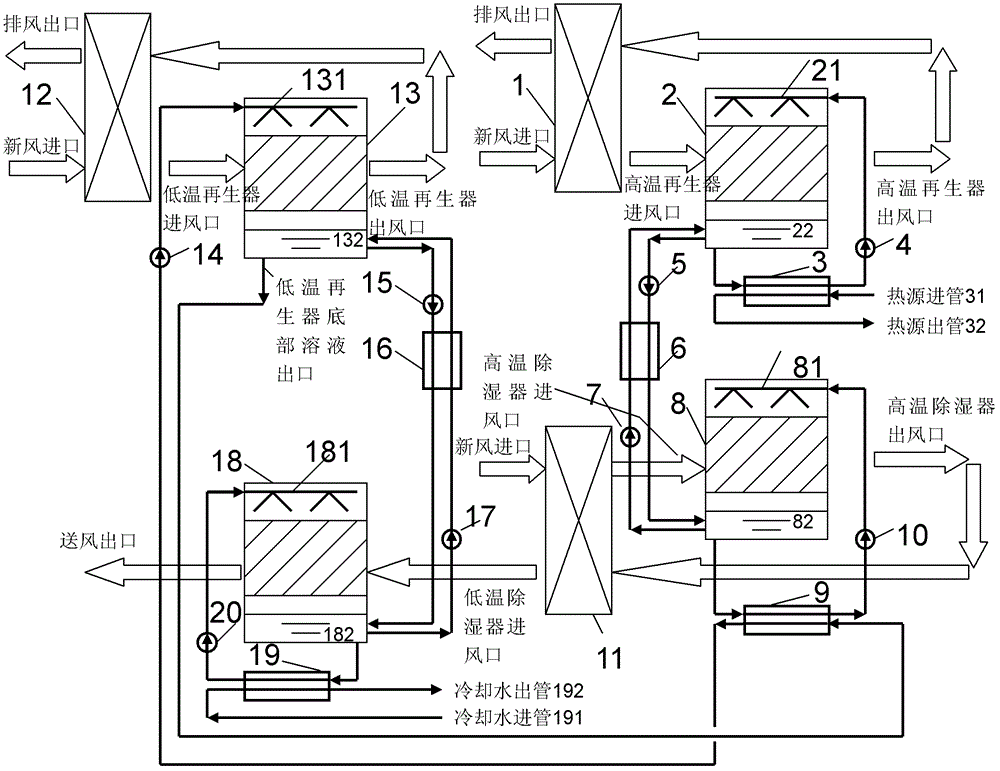
[0041] Embodiment 1. A double-effect solution dehumidification fresh air unit, including a high-temperature solution dehumidification circulation system and a low-temperature solution dehumidification circulation system; the high-temperature solution dehumidification circulation system and the low-temperature solution dehumidification circulation system are connected through a coupling heat exchanger 9 .

[0042] The high-temperature solution dehumidification circulation system includes high-temperature regenerator sensible heat recoverer 1, high-temperature regenerator 2, high-temperature regenerator heater 3, high-temperature regenerator solution circulation pump 4, high-temperature concentrated solution pump 5, high-temperature solution regenerator 6, high-temperature dilute Solution pump 7, high temperature dehumidifier 8, high temperature dehumidifier solution circulation pump 10 and high temperature dehumidifier sensible heat recovery device 11.

[0043] Sprayer I 21 is s...

Embodiment 2

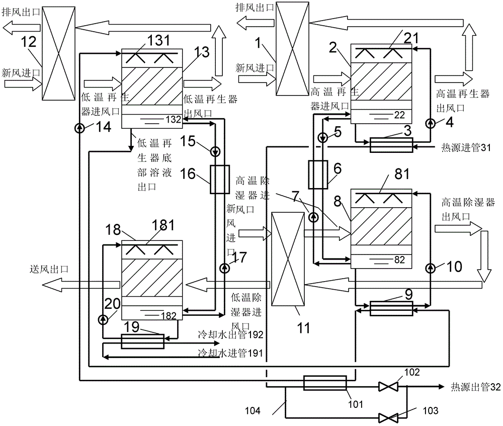
[0065] Embodiment 2, a kind of double-effect solution dehumidification fresh air unit, such as image 3 As shown, the difference from Embodiment 1 is that a set of low-temperature regenerator heater 101 and its bypass pipeline 104 are added. The two inlets of the low-temperature regenerator heater 101 are respectively connected to the heat source outlet of the high-temperature regenerator heater 3 and the solution outlet of the coupling heat exchanger 9 leading to the low-temperature regenerator 13, and the two outlets of the low-temperature regenerator heater 101 are respectively connected to the The sprayer III131 and the heat source outlet pipe 32 at the top of the low-temperature regenerator 13, a bypass pipeline 104 is set at both ends of the low-temperature regenerator heater 101, and the straight-through pipeline and the bypass pipeline 104 are respectively provided with regulating valves I 102 and Regulating valve II 103 . That is, a low-temperature regenerator heater...


PUM


Abstract

The invention discloses a dual-effect solution dehumidification fresh air unit which comprises a high-temperature solution dehumidification circulation system and a low-temperature solution dehumidification circulation system which are connected through a coupling heat exchanger (9), wherein the high-temperature solution dehumidification circulation system comprises a high-temperature regeneratorsensible heat recoverer (1), a high-temperature regenerator (2), a high-temperature regenerator heater (3), a high-temperature solution heat accumulator (6), a high-temperature dehumidification device (8), a high-temperature dehumidification device sensible heat recoverer (11) and the like; and the low-temperature solution dehumidification circulation system comprises a low-temperature regenerator sensible heat recoverer (12), a low-temperature regenerator (13), a low-temperature solution heat accumulator (16), a low-temperature dehumidification device (18), a low-temperature dehumidificationcooler (19) and the like. The dual-effect solution dehumidification fresh air unit can be used for reducing the irreversible loss of a solution dehumidification fresh air system in high-temperature heat source driving.

Description

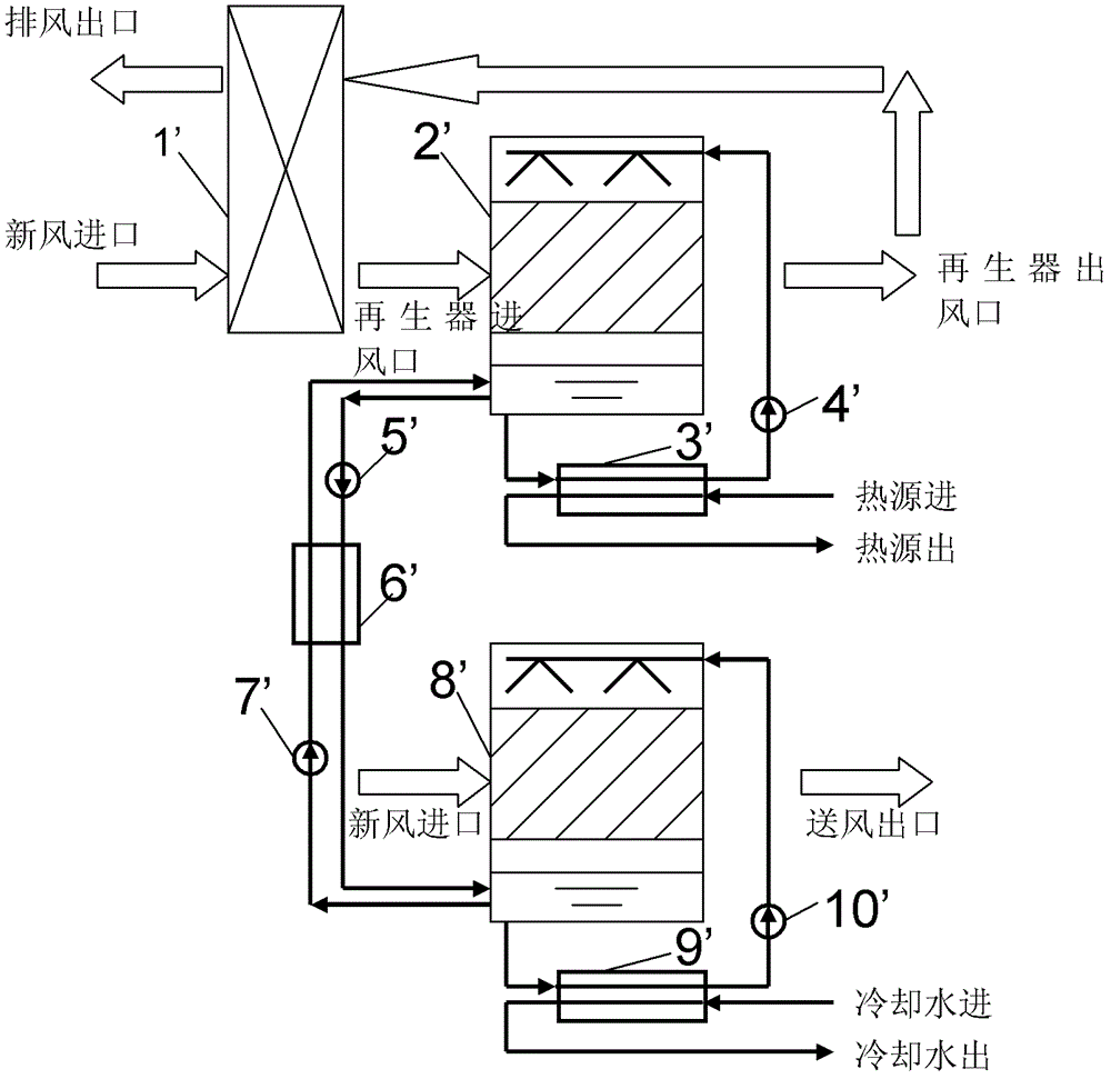
technical field [0001] The invention relates to a double-effect solution dehumidification fresh air unit, which belongs to the technical field of refrigeration and air conditioning equipment. Background technique [0002] The basic principle of the fresh air solution dehumidification unit currently used is as follows: figure 1 As shown, it mainly consists of regenerator sensible heat recoverer 1', regenerator 2', regenerator heater 3', regenerator solution circulation pump 4', concentrated solution pump 5', solution regenerator 6', dilute solution pump 7', dehumidifier 8', dehumidifier cooler 9' and dehumidifier solution circulation pump 10'. [0003] When the system is working, the fresh air enters the regenerator 2' after exchanging sensible heat with the exhaust air through the regenerator sensible heat recovery device 1', and the heat source supplies heat to the solution in the regenerator 2' through the regenerator heater 3' and is heated The final solution is sprayed...

Claims


Application Information

Patent Timeline
Patent Type & Authority Patents(China)
IPC IPC(8): F24F3/14F24F12/00F24F13/30
Inventor 王厉骆菁菁
Owner ZHEJIANG SCI-TECH UNIV
Learn More