Refractive Charged Particle Time-of-Flight Momentum Energy Mapping Method and Mapper

A charged particle and time-of-flight technology, which is applied in energy spectrometers, particle separation tubes, and radiation measurements, can solve problems such as deterioration of system energy resolution, reduction of system energy detection range, and collection efficiency of charged particles.

Inactive Publication Date: 2011-11-30
XI'AN INST OF OPTICS & FINE MECHANICS - CHINESE ACAD OF SCI
View PDF3 Cites 7 Cited by
  • Summary
  • Abstract
  • Description
  • Claims
  • Application Information

AI Technical Summary

Problems solved by technology

The second method can be realized by introducing a repelling field into the system. The disadvantage is that the existence of the repelling field will lead to the reduction of the system energy detection range and charged particle collection efficiency.
At the same time, the energy resolution of the system deteriorates sharply with the increase of the energy of the charged particles to be measured, which often becomes an important factor limiting the energy detection range of the system

Method used


Image

  • Refractive Charged Particle Time-of-Flight Momentum Energy Mapping Method and Mapper
  • Refractive Charged Particle Time-of-Flight Momentum Energy Mapping Method and Mapper
  • Refractive Charged Particle Time-of-Flight Momentum Energy Mapping Method and Mapper

Examples


Embodiment

[0231] In this part, we will describe the implementation of the present invention in detail in conjunction with specific examples, mainly the selection of the magnetic field, and at the same time quantitatively illustrate the superiority of the present invention in terms of its performance. The following content is divided into two parts according to the two working modes of the present invention - e mode and o mode.

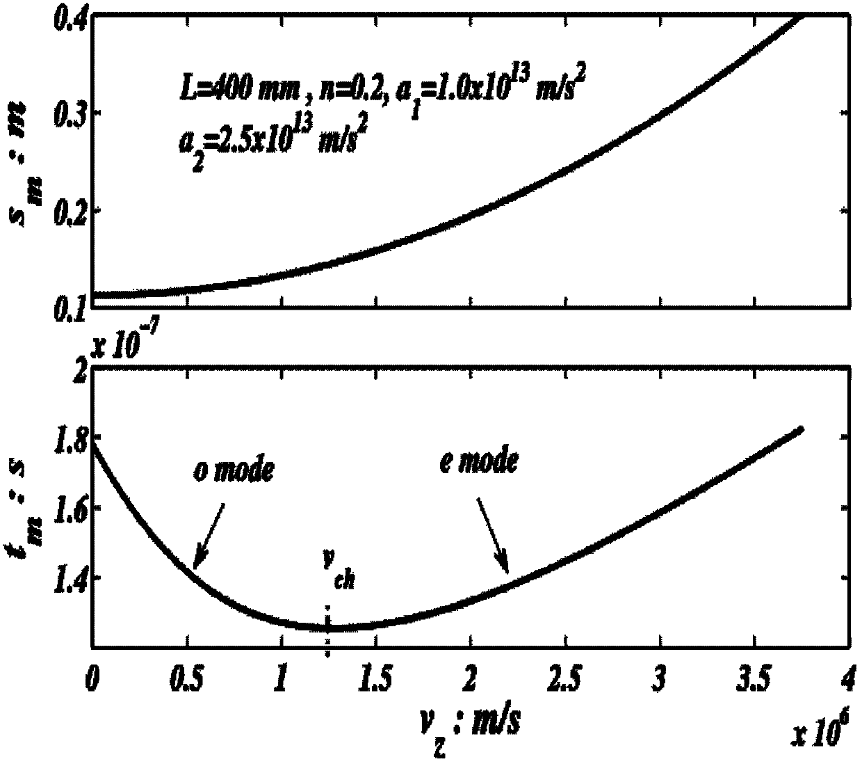
[0232] Consider a cylindrically symmetric mode-refractive charged particle time-of-flight momentum energy mapper whose parameters are set as: L=400mm, R=30mm, n=0.6, a 1 =2×10 13 m / s 2 , a 2 =a min , 10.0eV≤ε i ≤50.0eV. The charged particles we consider here are electrons. Established by formula (10), so the system works in o mode at this time. Then the conditional formula (17) and formula (18) selected by the magnetic field can obtain the effective magnetic field range corresponding to different magnetic node domains, as shown in Table 1. Image 6 The t...

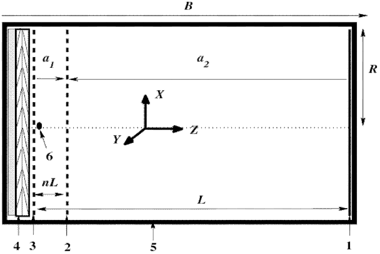

PUM


Abstract

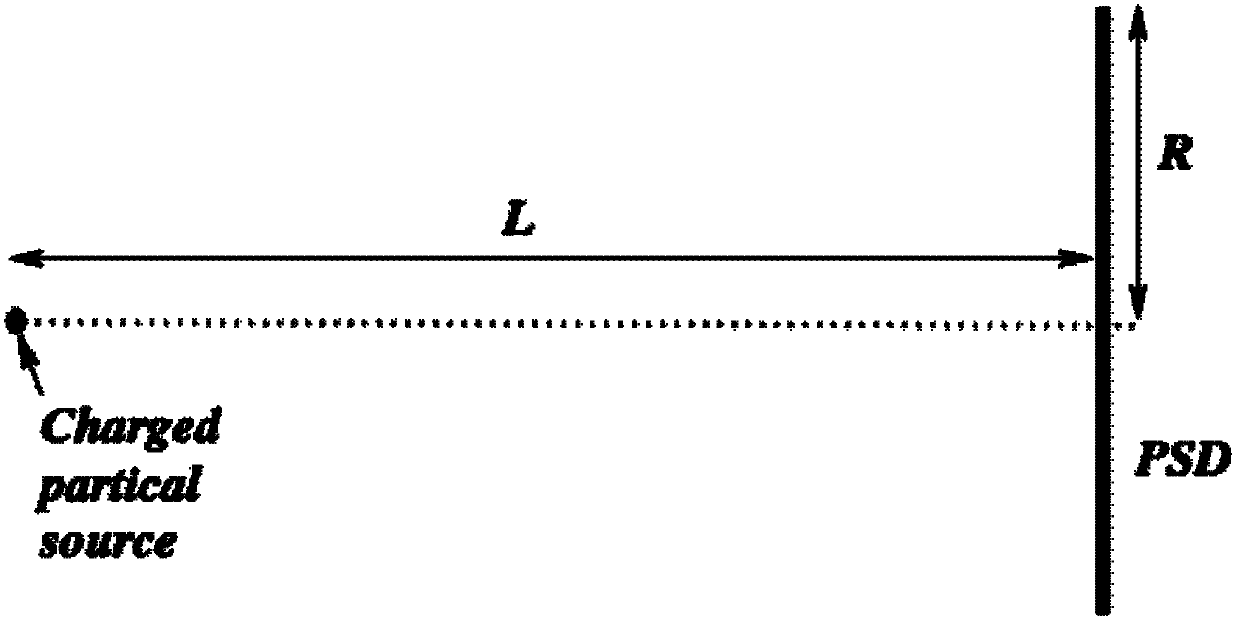
The invention relates to a method and a mapping meter for mapping flight time and momentum energy of a refraction type charged particle. The method comprises the following steps: 1) forming a reflection electric field which is uniform along axial direction in a vacuum test tube; 2) generating a charged particle by a charged particle source at one end of the vacuum test tube; 3) performing decelerated motion in the reflection electric field by the charged particle till an axial speed is reduced to zero; 4) immediately performing contrary accelerated motion in the reflection electric field by the charged particle till the charged particle arrives at a position sensing detector at the position of the charged particle source; and 5) detecting and recording the position information (x, y) and the flight time ttota1 of the charged particle by the position sensing detector, thereby finally mapping initial momentum and energy Epsilon i of the charged particle. The method and the mapping meterprovided by the invention are used for prolonging the flight time of the charged particle, by aiming at the bottleneck at the aspect of comprehensively promoting three parameters of energy resolution, energy detection range and charged-particle collecting efficiency of an existing charged particle flight time and momentum energy spectrometer.

Description

technical field [0001] The invention belongs to the technical field of charged particle time-of-flight energy spectrometer Background technique [0002] Time-Of-Flight (TOF) is a very important concept in electron optics. In electron optics energy analyzers, the energy dispersion of time-of-flight of charged particles in the system is often used to analyze and identify and finally obtain its own energy of. However, the Position-Sensitive Detector (PSD), which has been successfully developed in recent years, can simultaneously record the time-of-flight information of particles and the position information of their impact on the detector. According to the mapping between the time and position information and the initial velocity of charged particles The initial energy and initial momentum of the particle can be obtained at the same time. This is the basic principle of charged particle time-of-flight momentum energy spectrometer. The main performance parameters of charged pa...

Claims


Application Information

Patent Timeline
Patent Type & Authority Applications(China)
IPC IPC(8): H01J49/00H01J49/44G01T1/00
Inventor 王超田进寿刘虎林曹希斌温文龙徐向晏王俊锋
Owner XI'AN INST OF OPTICS & FINE MECHANICS - CHINESE ACAD OF SCI
Why Eureka
Try Eureka