
Fixing mechanism for solar panels

A solar panel and fixing mechanism technology, which is applied to the fixed base/support of solar collectors, solar thermal power generation, solar thermal energy, etc., can solve the problems of low versatility and various forms, and achieve strong versatility and easy installation Fast, simple effects

Inactive Publication Date: 2011-11-30
SAMIL POWER
View PDF4 Cites 7 Cited by
  • Summary
  • Abstract
  • Description
  • Claims
  • Application Information

AI Technical Summary

Problems solved by technology

[0003] The purpose of the present invention is to provide a solar cell panel fixing mechanism to solve the problems of low versatility and various forms of the current solar cell panel fixing device, which has the advantages of strong versatility and simple structure

Method used


Image

  • Fixing mechanism for solar panels
  • Fixing mechanism for solar panels
  • Fixing mechanism for solar panels

Examples


Embodiment Construction

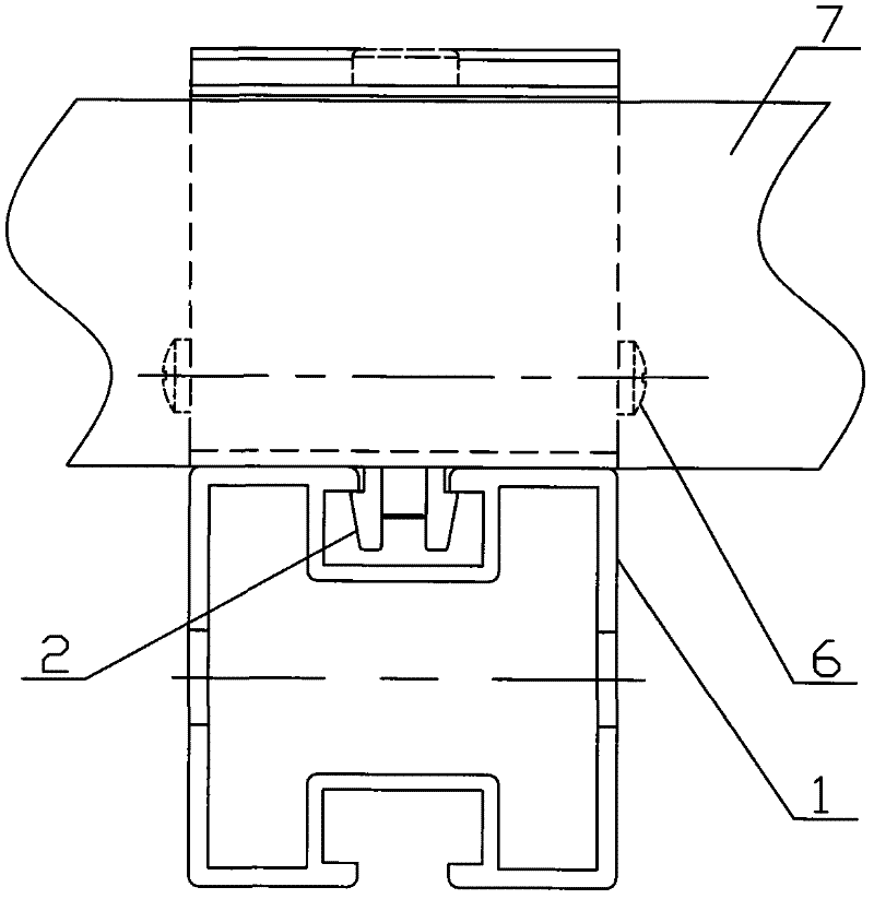
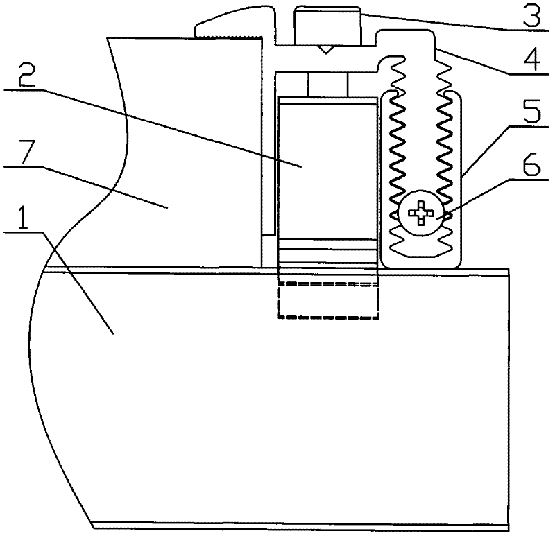
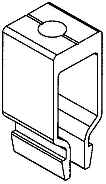
[0014] Such as Figure 1~3 In the shown embodiment, the fixing mechanism of a single solar cell panel according to the present invention is composed of a guide rail 1 , a buckle 2 , a bolt 3 , a side pressure code 4 , a side pressure code seat 5 and a limit screw 6 . When installing, place the solar panel 7 on the guide rail 1, and the buckle 2 is stuck in the chute of the guide rail 1 through the micro-deformation of the two hooks provided by it. Insert the side pressure code 4 into the toothed groove of the side pressure code seat 5 from the side, and then screw in the screws 6 on both sides of the side pressure code 4 to prevent it from coming out of the toothed groove. Then use the bolt 3 to connect the fastening side pressure code 4 and the buckle 2. After the bolt 3 is tightened, the screw head of the bolt 3 is just between the two hooks of the buckle 2, and the screw can limit the compression deformation of the buckle, so that Prevent the buckle 2 from coming out of th...


PUM


Abstract

The invention discloses a fixing mechanism for a solar battery panel, which includes a guide rail, on which a buckle is installed, and the buckle is stuck in a slide groove of the guide rail through the slight deformation of two hooks provided on the guide rail. The buckle connects the middle part of the side press code through bolts. One end of the side press code adopts an inverted L-shaped structure that presses the solar panel on the guide rail, and the other end adopts a rack-shaped structure, and the side is inserted with matching teeth. In the edge pressing seat of the shaped groove. According to the thickness of the solar panel, adjust the tooth-shaped matching position of the side pressing code and the side pressing code seat, which can adapt to various specifications of solar panels and has the advantage of strong versatility; In the groove, insert the side pressing code into the side pressing code seat, and then connect and fasten with the buckle through bolts, which is quick to install and simple in structure.

Description

technical field [0001] The invention relates to a fixing device for solar photovoltaic power generation equipment, in particular to a fixing mechanism for solar battery panels. Background technique [0002] Solar power generation is divided into photothermal power generation and photovoltaic power generation. Generally speaking, solar power generation refers to solar photovoltaic power generation, referred to as "photoelectricity". Photovoltaic power generation is a technology that uses the volt effect of light at the semiconductor interface to directly convert light energy into electrical energy. The key component of this technology is a solar cell. After the solar cells are connected in series, they can be packaged and protected to form a large-area photovoltaic module, and then cooperate with power controllers and other components to form a photovoltaic power generation device. Photovoltaic modules are commonly known as solar panels. When in use, solar panels need to be ...

Claims


Application Information

Patent Timeline
Patent Type & Authority Applications(China)
IPC IPC(8): H01L31/048
CPCY02E10/50F24S25/30F24S25/634F24S25/636F24S2025/6008Y02E10/47
Inventor 夏登福崔佩聚
Owner SAMIL POWER
Learn More