Induction lighting fixtures and induction lighting systems

A technology for induction lighting and lamps, applied in the field of induction lighting lamps and induction lighting systems, can solve problems such as high maintenance costs, potential safety hazards, and neglect of daily maintenance, so as to reduce installation and maintenance costs, eliminate potential safety hazards, and achieve good lighting effects. Effect

Inactive Publication Date: 2011-11-30
HEFEI SANCHUAN AUTOCONTOL ENG
View PDF6 Cites 30 Cited by
  • Summary
  • Abstract
  • Description
  • Claims
  • Application Information

AI Technical Summary

Problems solved by technology

[0006] 1. Installing an additional emergency lighting system in addition to the daily lighting system will inevitably increase the installation cost
Moreover, the emergency lighting system must be regularly tested, and the light source and battery must be replaced in time according to the service life, and the maintenance cost is very high.
Even if the emergency lighting system is regularly maintained as required, due to its low utilization rate, even if there is damage to the lamps, it cannot be found in time, and there are always potential safety hazards
In addition, many builders took chances, only pursued low prices and light quality, and neglected daily maintenance, which is very easy to cause accidents when disasters occur.
[0007] 2. When switching from daily lighting to emergency lighting, the brightness of the lighting will change suddenly, which may easily cause panic
After a disaster occurs and the power is cut off, the building is dark, only the corridors and stairwells reveal faint li

Method used


Image

  • Induction lighting fixtures and induction lighting systems
  • Induction lighting fixtures and induction lighting systems
  • Induction lighting fixtures and induction lighting systems

Examples


Embodiment 1

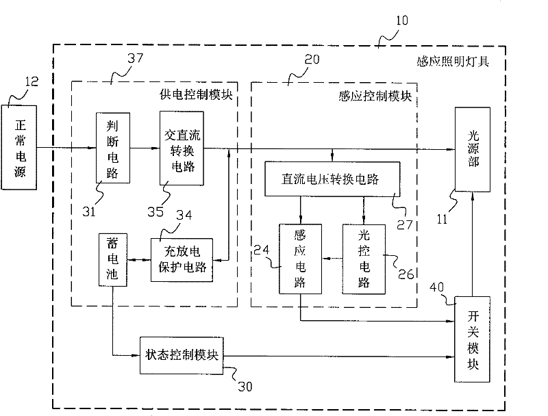
[0038] attached figure 1 It is a block diagram of the induction lighting fixture 10 according to Embodiment 1 of the present invention.

[0039] as attached figure 1 As shown, the induction lighting fixture 10 is composed of a light source unit 11 , a power supply control module 37 , an induction control module 20 , a state setting module 30 , a switch module 40 and a battery 50 .

[0040]Wherein, the light source part 11 adopts a low-power LED lamp 13 . The normal power supply 12 is the commercial power of AC220V.

[0041] The power supply control module 37 is connected to the mains and the storage battery 50 at the same time, and is equipped with a judgment circuit 31 , an AC / DC conversion circuit 35 and a charge / discharge protection circuit 34 . In the daily lighting mode, the power supply control module 37 receives power from the mains, and converts the mains power into a 12V low-voltage direct current through an AC-to-DC conversion circuit 35 to supply power to the ind...

Embodiment 2

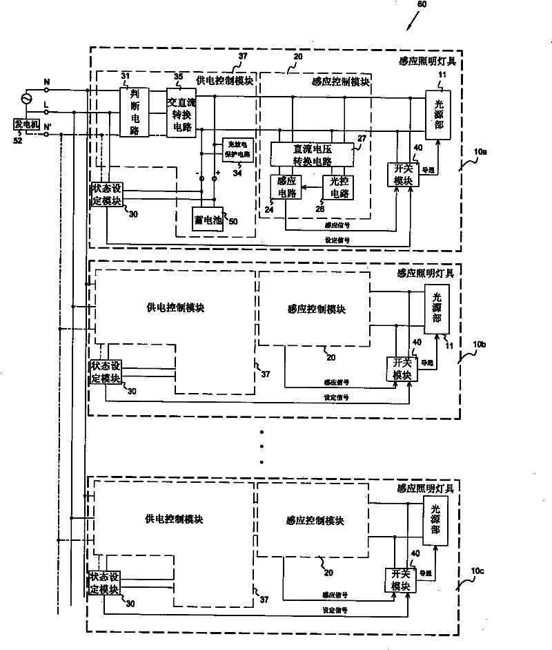
[0056] attached image 3 It is a schematic circuit diagram of the induction lighting system 60 according to Embodiment 2 of the present invention. attached Figure 4-5 It is a circuit diagram of an induction lighting fixture 10 in the induction lighting system 60 of the second embodiment. The following will be combined with Figure 3-5 , the working process of the induction lighting system 60 is described in detail.

[0057] as attached image 3 As shown, like Embodiment 1, each induction lighting fixture 10 in Embodiment 2 includes a light source unit 11, a power supply control module 37, an induction control module 20, a state setting module 30, a switch module 40, and a storage battery 50, and these The structure and function of the components are also basically the same as in Embodiment 1. A plurality of such induction lighting fixtures 10 are connected in parallel and share a set of power supplies, thus forming an induction lighting system 60 .

[0058] The differen...

Embodiment 3

[0085] attached Figure 7 It is a block diagram of the induction lighting system 60 according to the third embodiment of the present invention. as attached Figure 7 As shown, like Embodiment 2, each induction lighting fixture 10 in Embodiment 3 includes a light source unit 11, a power supply control module 37, an induction control module 20, a state setting module 30 and a switch module 40, and the structures of these components And the function is also the same as in Embodiment 2.

[0086] The difference between Embodiment 3 and Embodiment 2 is that, in Embodiment 3, each induction lighting fixture 10 does not separately include a storage battery 50 used as an emergency power supply and a generator 52 that must be manually turned on, but the entire induction lighting system 60 A UPS power supply 51 is shared, and the UPS power supply 51 is connected to the commercial power supply and a group of storage batteries 50 at the same time. When the mains power is cut off, the UP...


PUM


Abstract

The invention discloses an induction lighting lamp, which comprises an induction control module, a state setting module, a switch module, a light source part and a power supply and control module. The power supply and control module outputs power from a normal power supply; the induction control module inducts an external signal and generates an induction signal; the switch module receives the induction signal and lightens the light source part; when the normal power supply is cut off, the power supply and control module outputs power from an emergency power supply; the state setting module receives a signal from the power supply and control module and generates a setting signal; and the switch module is conducted when receiving the setting signal, and continuously brightens the light source part. The induction lighting lamp integrates a normal light system and an emergence lighting system; and the two systems use one light source so that the mounting and maintenance cost is reduced. The normal lighting is in the induction type, so that the energy-saving effect is excellent; and in the emergency lighting state, the induction lighting lamp is automatically switched into a long lighting mode so as to ensure security. The invention further discloses an induction lighting system using the induction lighting lamp.

Description

technical field [0001] The invention relates to an induction lighting fixture and an induction lighting system using the induction lighting fixture, in particular to an induction lighting fixture and an induction lighting system which have both daily lighting functions and emergency lighting functions. Background technique [0002] The function of emergency lighting is to provide lighting for fire fighting and rescue work in case of fire, earthquake and other disasters, so as to ensure the safety of people in the building. Especially for the increasing number of high-rise buildings in today's cities, once a disaster occurs, its firefighting and rescue work is very difficult, and the requirements for the lighting quality and stability of the lighting system are particularly high. [0003] However, the emergency lamps and emergency lighting systems currently on the market are not satisfactory in terms of lighting quality, stability and maintenance costs. [0004] The key reas...

Claims


Application Information

Patent Timeline
IPC IPC(8): H05B37/02
CPCY02B20/40
Inventor 李保高劲松储可明
Owner HEFEI SANCHUAN AUTOCONTOL ENG
Why Eureka
Try Eureka