A die-cutting machine suitable for roll materials using a combined die-cutting method

A combined die-cutting machine technology, applied in metal processing and other directions, to achieve the effect of reducing manufacturing cost and use cost, reducing labor intensity and enhancing stability

Inactive Publication Date: 2011-12-07
杜建刚
View PDF0 Cites 14 Cited by
  • Summary
  • Abstract
  • Description
  • Claims
  • Application Information

AI Technical Summary

Problems solved by technology

The resistance unit controls the tension of the

Method used


Image

  • A die-cutting machine suitable for roll materials using a combined die-cutting method
  • A die-cutting machine suitable for roll materials using a combined die-cutting method
  • A die-cutting machine suitable for roll materials using a combined die-cutting method

Examples


Embodiment Construction

[0029] The present invention will be further described in detail below in conjunction with the accompanying drawings and specific embodiments.

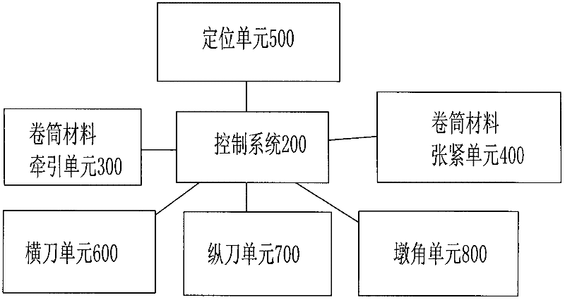
[0030] like figure 1 As shown, a die-cutting machine suitable for roll materials using a combined die-cutting method in the present invention includes a frame 100, a roll material traction unit 300 respectively connected to a control system 200, and a roll material tensioning unit. Unit 400, positioning unit 500, horizontal knife unit 600, vertical knife unit 700 and pier corner unit.

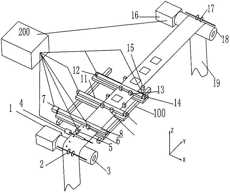
[0031] like figure 2 As shown, the roll material pulling unit 300 controls the positive movement of the roll material 19 along the Y direction (ie, the length direction) of the roll material, and the roll material tensioning unit 400 is used to move the roll material 19 The reversal of the Y direction provides a tension force to prevent the roll material 19 from shaking and sagging. The roll material pulling unit 300 and the roll material tensioni...


PUM


Abstract

The invention discloses a die-cutting machine suitable for roll materials adopting a combined die-cutting method, comprising a frame, a roll material pulling unit, a roll material tensioning unit, and a positioning unit respectively connected with a control system , a horizontal knife unit, a vertical knife unit and a pier corner unit, wherein: the pier corner unit includes a pier corner bar, a pier corner clutch mechanism, and a pier corner tool holder and a cutter arranged on the pier corner bar, the The pier angle bar is arranged along the X direction of the frame, and the pier angle clutch mechanism is an electromagnet or a linear motion motor connected with the pier angle bar, and the electromagnet or the linear motion The motor is connected with the control system. The die-cutting machine of the present invention can solve the problem of high cost of die-cutting tools in the prior art, long production cycle, poor durability, complicated machine adjustment, heavy machine, low and unstable die-cutting quality, low die-cutting speed, waste of materials, Not suitable for technical problems such as small batch production.

Description

technical field [0001] The invention relates to a die-cutting machine, in particular to a die-cutting machine suitable for roll materials which adopts a combined die-cutting method. Background technique [0002] Die-cutting machines are usually used in the manufacturing process of roll stickers and similar material products. Die-cutting machines are divided into flat and flat, round and round, Flat pressed round, round flattened die cut form. At present, the flat die-cutting form is more commonly used in die-cutting machines. like Pic 4-1 and Figure 4-2 The structure of the flat-pressed die-cutting type shown includes a die-cutting plate 43 located below the upper platen 41 and a lower backing plate 42 located below the receiving medium 40, and the flat-pressed die-cutting depends on the downward direction of the die-cutting plate 43 It is realized by stamping. The characteristics of the flat die-cutting are: there are high technical requirements for the leveling of the...

Claims


Application Information

Patent Timeline
IPC IPC(8): B26F1/38B26F1/44B26D7/01B26D7/26B26D5/26
Inventor 杜建刚
Owner 杜建刚
Why Eureka
Try Eureka