Method for excavating tunnel in high liquid limit soil

A technology of tunnel excavation and high liquid limit soil, applied in the field of improvement of CRD excavation method, can solve problems affecting construction progress, manual excavation, primary lining damage, etc., improve construction safety and facilitate excavation , Improve the effect of construction efficiency

Active Publication Date: 2013-10-23
GUANGDONG PROVINCIAL CHANGDA HIGHWAY ENG
View PDF5 Cites 0 Cited by
  • Summary
  • Abstract
  • Description
  • Claims
  • Application Information

AI Technical Summary

Problems solved by technology

[0003] The above-mentioned tunnels have been constructed using the CRD method in the early stage, and there are mainly the following problems: (1) The process is relatively simple, but there are too many cycles, and manual excavation is required , which seriously affects the construction progress; (2) According to the requirements of the tunnel technology disclosure, the distance between the tunnel face and the inverted arch should not exceed 12m, and the inverted arch will be constructed after the excavation of the full section is completed about 10m, which requires that the pouring of the inverted arch must be completed in advance. Once the inverted arch is poured, the slag discharge dump truck cannot enter the tunnel face, that is, the footage cannot be carried out, which affects the excavation progress; (3) Even if the excavator and dump truck can reach the tunnel face, it is impossible to make the inverted arch closely follow the tunnel face. The primary lining is inevitably directly rolled by mechanical equipment, which is undoubtedly a kind of damage to the primary lining, which is the most taboo in tunnel construction.

Method used


Image

  • Method for excavating tunnel in high liquid limit soil
  • Method for excavating tunnel in high liquid limit soil
  • Method for excavating tunnel in high liquid limit soil

Examples


Embodiment Construction

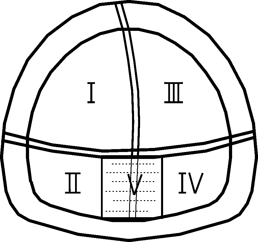
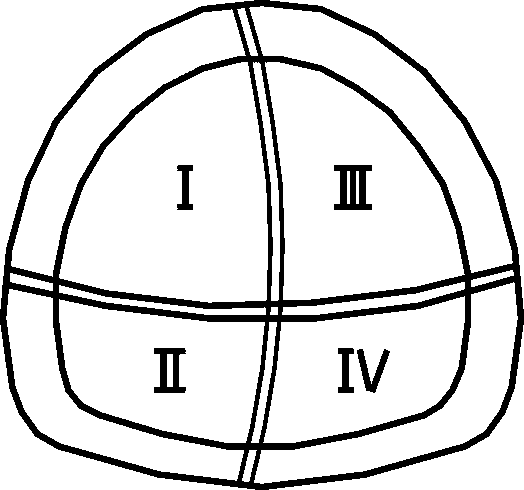
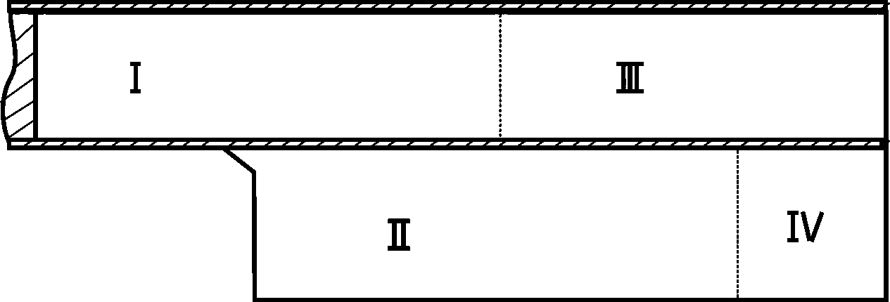
[0020] Such as figure 1 Shown, a kind of tunnel excavation method in high liquid limit soil, comprises the following steps:

[0021] A. The excavator is supplemented by manual excavation of the surrounding rock above the side wall, and the middle partition wall still needs to be installed. When excavating, first excavate the left upper part I, and immediately carry out shotcrete protection for the face of the tunnel and excavation after completion. Fresh surrounding rock, spray anchor support for the middle partition wall;

[0022] B. Install the I-beam on the upper part I on the left side, then install the bolts and grout, and spray steel fiber concrete to complete the initial support of the vault of the I part;

[0023] C. Excavate the upper part III on the right side of the tunnel, using the excavator as the main method combined with manual excavation. After excavating for a certain distance, spray concrete protection on the face of the tunnel and the surrounding rock of ...


PUM


Abstract

The invention discloses a method for excavating a tunnel in high liquid limit soil. The method comprises the following steps of: A, excavating the upper part of the left side of the tunnel; B, performing primary support on an arch crown in the excavated section; C, excavating the upper part of the right side of the tunnel; D, finishing the primary support of the arch crown; E, excavating the lower part of the tunnel, namely a lower left side part, a core soil part and a lower right side part, firstly excavating the lower left side part, secondly excavating the lower right side part, and finally excavating the core soil part; and F, assembling reinforcement on an inverted arch, mounting a template, pouring C25 concrete to finish a second liner of the inverted arch, and backfilling the concrete. In the method, a manual hand-held wind tunnel excavating tool is mainly replaced by an excavator for excavation supplemented by manual modification, so that construction efficiency is greatly improved; the middle core soil part is increased through inverted arch excavation, so that the stability of surrounding rocks in the sealing ring formation process is ensured, and construction safety isgreatly improved; and due to the application of the method, construction efficiency is improved, and construction cost is reduced.

Description

technical field [0001] The invention relates to a tunnel excavation method in high liquid limit soil, in particular to an improvement on the CRD excavation method. Background technique [0002] CRD method excavation mainly adopts manual excavation, and blasting is strictly prohibited unless special circumstances such as boulders are encountered during construction. Steel pipe scaffolding should be used to set up the construction platform, manual hand-held pneumatic excavation tools should be used for excavation, excavators should remove slag, and dump trucks should remove slag. Tunnel excavation is divided into left and right pilot pits and upper and lower steps, and the excavation interval of each part is 3-5m, which is adjusted according to specific conditions in actual construction. Its construction process is as follows: figure 2 and image 3 As shown, (1) Excavate part I (①), spray C25 concrete protection on the tunnel face, then install I-beams, install anchor rods,...

Claims


Application Information

Patent Timeline
Patent Type & Authority Patents(China)
IPC IPC(8): E21D9/00E21D11/00E21D11/10E21D20/02
Inventor 曹亮宏吴定略陈培冲吕世明卢自立孙江涛徐志元徐光波曹志月
Owner GUANGDONG PROVINCIAL CHANGDA HIGHWAY ENG
Why Eureka
Try Eureka