Drilling slag dust collector for underground coal mine

A technology for dust collectors and coal mines, applied in dust prevention, mining equipment, earthwork drilling, etc., can solve the problems of high gas concentration, large equipment volume, harsh environment, etc., and achieve the effect of light weight, small volume and simple structure

Inactive Publication Date: 2011-12-07
YANGZHOU YINJIANG MINING EQUIP
View PDF5 Cites 3 Cited by
  • Summary
  • Abstract
  • Description
  • Claims
  • Application Information

AI Technical Summary

Problems solved by technology

Although the flow rate of the blowing dust gas is not large, the energy of the compressed air is large, and the impact force of the formed airflow is strong, and the amount of dust carried is as high as 3000mg / m 3 Above, the environment of the working face is very harsh, which seriously threatens the health of the operators; the gas concentration of the jet air is high, and due to the high safety production requirements, the dust reduction method of the dust blowing process prohibits fan extraction
[0003] In order to improve the serious environmental pollution problem in dry drilling, the current method is to install a dust collector for the drill pipe casing at the hole of the dry drilling. The small casing goes deep into the coal seam, and the large casing is close to the wall of the roadway. The blowing dust of compressed air is sprayed out along the gap between the drill pipe and the small casing into the large casing, and the dust is sprayed in the large casing to reduce the dust. The dust removal efficiency is between 50% and 60%. Although the dust reduction effect is obvious, it is difficult to achieve work Environmental Hygiene Standards
At present, there are other forms of process equipment for orifice dust removal, such as multi-stage non-powered orifice dust collector (200920032546.X), mine wet orifice dust collector (200620110816.0), but due to the large size of the equipment, it is difficult to quickly remove, install and Difficult to carry and difficult to adapt to the needs of frequent replacement of drilling positions

Method used


Image

  • Drilling slag dust collector for underground coal mine
  • Drilling slag dust collector for underground coal mine
  • Drilling slag dust collector for underground coal mine

Examples


Embodiment 1

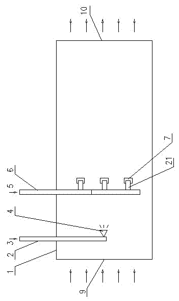
[0029] Such as figure 1 As shown, it is a coal mine underground drilling slag removal dust collector, including a straight pipe 1, a water pipe 2 and a gas pipe 6, the front end of the straight pipe 1 is an air inlet 9, and the rear end of the straight pipe 1 is an exhaust port 10. The water pipe 2 is placed on the straight pipe 1 , and one end of the water pipe 2 in the straight pipe 1 is connected to the water atomizing nozzle 4 , and the water atomizing nozzle 4 faces the exhaust port 10 . The gas pipe 6 is placed on the straight pipe 1, and the gas pipe 6 in the straight pipe 1 is connected with three branch pipes 21, each branch pipe 21 is respectively arranged parallel to the central axis of the straight pipe 1, and the other end of each branch pipe 21 is respectively The gas shower heads 7 are connected, and each gas shower head 7 faces the exhaust port 10 respectively. The water atomizing nozzle 4 is arranged between the air inlet 9 and the gas nozzle 7 .

[0030] Hi...

Embodiment 2

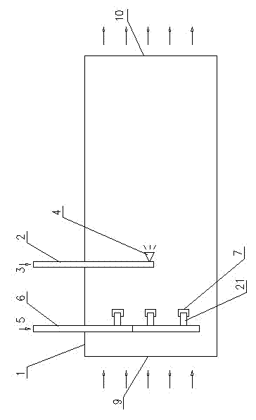
[0032] Such as figure 2 As shown, the gas nozzle 7 is arranged between the air inlet 9 and the water atomization nozzle 4 . All the other structures are with embodiment 1.

Embodiment 3

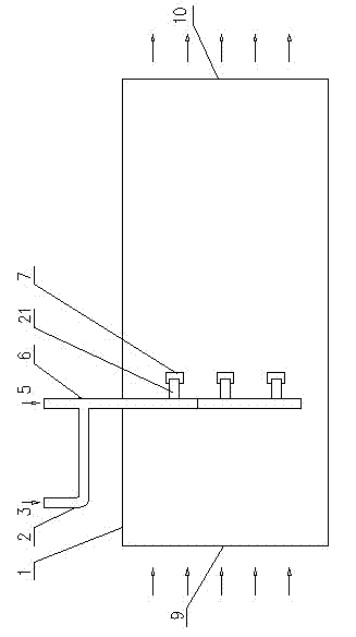
[0034] Such as image 3 As shown, it includes a straight pipe 1, a water pipe 2 and a gas pipe 6. The front end of the straight pipe 1 is an air inlet 9, and the rear end of the straight pipe 1 is an exhaust port 10. The gas pipe 6 is placed on the straight pipe 1, and the gas pipe 6 in the straight pipe 1 is connected with three branch pipes 21, each branch pipe 21 is respectively arranged parallel to the central axis of the straight pipe 1, and the other end of each branch pipe 21 is respectively The gas shower heads 7 are connected, and each gas shower head 7 faces the exhaust port 10 respectively. The water pipe 2 is next to the gas pipe 6 outside the straight pipe 1. The water pipe 2 and the gas pipe 6 are combined into one pipe. In this way, the compressed air 5 and the high-pressure water 3 (the volume occupied by the high-pressure water is very small) are sprayed at the gas nozzle 7 at high speed, and the water is atomized into droplets during the high-speed spraying ...


PUM


Abstract

The utility model relates to a drilling slag removal dust remover for underground coal mines, which relates to a ventilation and dust removal device for underground coal mines. The gas outlet end of the gas pipe is arranged in the straight pipe, and at least one gas nozzle is arranged at the gas outlet end of the gas pipe, and each gas nozzle faces the exhaust port respectively. The advantages of the present invention are: (1) High-pressure gas injection is adopted, the dust collector has no moving parts and electrical components, and the use environment is not limited by gas concentration; (2) The dust collector has simple structure, small volume, light weight, , Quick and convenient installation; (3) The dust removal efficiency of the dust collector is not less than 95% under any dust concentration in the intake air, and there will be no problem of dust collector clogging.

Description

technical field [0001] The invention relates to an underground ventilation and dust removal device for coal mines, which is mainly used for dry drilling dust removal on coal seam walls of underground roadways in coal mines, dust reduction by anchor spraying technology, and belt coal transportation and reloading points. Background technique [0002] The existence of gas in the coal seam threatens the safe mining of coal. Drilling holes on the wall of the underground roadway in coal mines to drain the gas in the coal seam has become an important link in the safe mining of coal. For some soft coal seams, only dry drilling can be used, and the compressed air blowing process is used to make the coal powder and compressed air generated during drilling spray out along the gap between the drill pipe and the hole wall. Although the flow rate of the blowing dust gas is not large, the energy of the compressed air is large, and the impact force of the formed airflow is strong, and the a...

Claims


Application Information

Patent Timeline
Patent Type & Authority Applications(China)
IPC IPC(8): E21F5/04E21F5/20
Inventor 王助良盛华兴丁燕琴张建新
Owner YANGZHOU YINJIANG MINING EQUIP
Why Eureka
Try Eureka