Deduster

A technology for dust collectors and mixers, which is used in dust prevention, safety devices, mining equipment, etc., can solve the problems of large equipment volume, high gas concentration, and difficulty in adapting to frequent replacement of drilling positions, and achieves the effect of simple structure.

Inactive Publication Date: 2011-01-26
YANGZHOU YINJIANG MINING EQUIP
View PDF2 Cites 15 Cited by
  • Summary
  • Abstract
  • Description
  • Claims
  • Application Information

AI Technical Summary

Problems solved by technology

Although the flow rate of the blowing dust gas is not large, the energy of the compressed air is large, and the impact force of the formed airflow is strong, and the amount of dust carried is as high as 3000mg / m 3 Above, the environment of the working face is very harsh, which seriously threatens the health of the operators; the gas concentration of the jet air is high, and due to the high safety production requirements, the dust reduction method of the dust blowing process prohibits fan extraction
[0003] In order to improve the serious environmental pollution problem in dry drilling, the current method is to install a dust collector for the drill pipe casing at the hole of the dry drilling. The small casing goes deep into the coal seam, and the large casing is close to the wall of the roadway. The blowing dust of compressed air is sprayed out along the gap between the drill pipe and the small casing into the large casing, and the dust is sprayed in the large casing to reduce the dust. The dust removal efficiency is between 50% and 60%. Although the dust reduction effect is obvious, it is difficult to achieve work Environmental Hygiene Standards
At present, there are other forms of process equipment for orifice dust removal, such as multi-stage non-powered orifice dust collector (200920032546.X), mine wet orifice dust collector (200620110816.0), but due to the large size of the equipment, it is difficult to quickly remove, install and Difficult to carry and difficult to adapt to the needs of frequent replacement of drilling positions

Method used


Image

  • Deduster
  • Deduster
  • Deduster

Examples


Embodiment 1

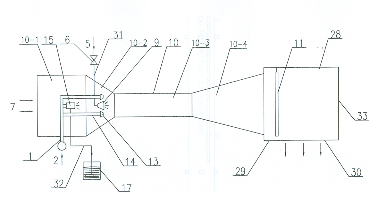
[0027] Such as figure 1 As shown, it is a dust collector, including a Venturi mixer 10, and the Venturi mixer 10 includes an air inlet chamber 10-1, a shrinkage pipe section 10-2, a straight pipe section 10-3 and a conical diffuser section 10-4 . A high-pressure gas inlet pipe 1 is arranged in the air inlet chamber 10-1, the outer end of the high-pressure gas inlet pipe 1 is arranged outside the air inlet chamber 10-1, and the inner end of the high-pressure gas inlet pipe 1 is connected with two venturi tubes for mixing A straight pipe 14 parallel to the central axis of the device 10, the other end of the straight pipe 14 is equipped with a high-pressure gas nozzle 13, and the outlet of the high-pressure gas nozzle 13 is arranged at the shrinkage pipe section 10-2.

[0028] The high-pressure gas inlet pipe 1 is connected to the ejector 15, and the ejector 15 is connected to the liquid storage tank 17 through the connecting pipe 32, and the liquid storage tank 17 is arranged o...

Embodiment 2

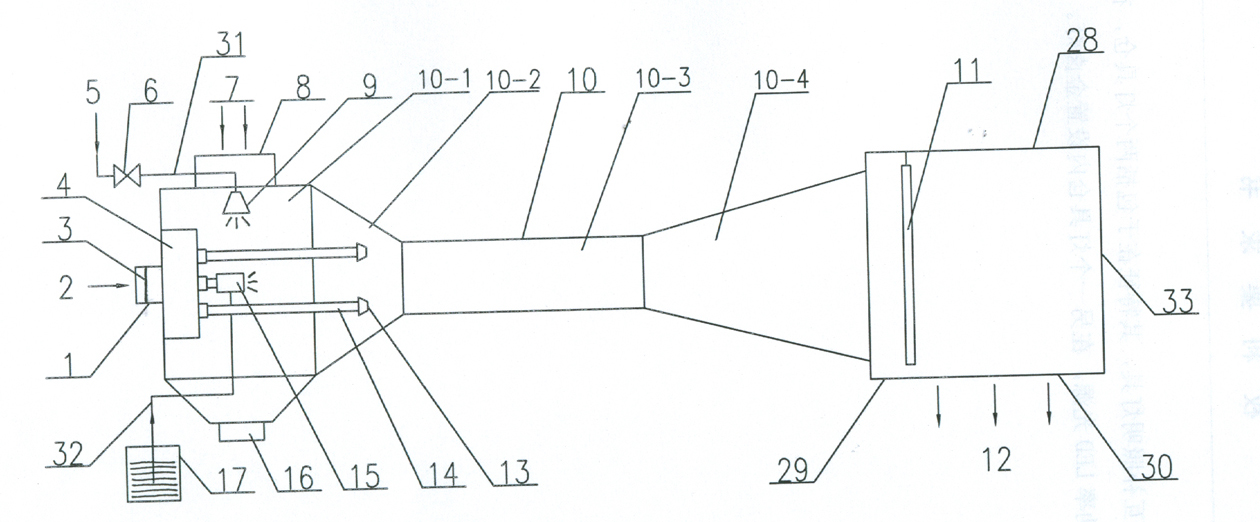
[0032] Such as figure 2 As shown, a high-pressure gas distribution chamber 4 is set between the high-pressure gas inlet pipe 1 and the straight pipe 14 , the high-pressure gas distribution chamber 4 is set in the air intake chamber 10 - 1 , and each straight pipe 14 is arranged at one end of the high-pressure gas distribution chamber 4 . The upper end of the air intake chamber 10 - 1 is connected to the dust-laden airflow inlet pipe 8 , and the axis of the dust-laden airflow inlet pipe 8 is perpendicular to the axis of the Venturi tube mixer 10 . A first filter screen 3 is arranged in the high-pressure gas inlet pipe 1 . The water inlet pipe 31 is passed through the air inlet chamber 10-1, and the water atomization nozzle 9 is arranged in the air inlet chamber 10-1. The lower end of the air inlet chamber 10-1 is connected with the slag discharge port 16. All the other structures are with embodiment 1.

[0033] The high-pressure gas 2 enters the high-pressure gas distributi...


PUM


Abstract

The invention discloses a deduster, relating to an underground dust removal and ventilation device. The deduster comprises a Venturi tube mixer, wherein the Venturi tube mixer comprises an inlet chamber, a shrinking tube section, a straight tube section and a tapered diffusion section; the inlet chamber is internally provided with a high-pressure gas inlet tube; the outer end of the high-pressure gas inlet tube is arranged outside the inlet chamber, and the inner end of the high-pressure gas inlet tube is connected with at least one straight tube which is in parallel with the central axis of the Venturi tube mixer; the other end of the straight tube is provided with a high-pressure gas shower nozzle, and the outlet of the high-pressure gas shower nozzle is arranged in the Venturi tube mixer; the high-pressure gas inlet tube is also connected with an ejector, the ejector is connected with a liquid storage tank through a connecting tube, and the liquid storage tank is arranged outside the inlet chamber; the Venturi tube mixer is also provided with an inlet tube; the inlet tube is provided with a valve, and the inner end of the inlet tube is connected with a water atomization shower nozzle; and the water atomization shower nozzle is arranged in the Venturi tube mixer. The deduster has the advantages of simple structure, small size, light weight, convenient carrying and high dust collection efficiency.

Description

technical field [0001] The invention relates to an underground ventilation and dust removal device for coal mines, which is mainly used for dry drilling dust removal on coal seam walls of underground roadways in coal mines, dust reduction by anchor spraying technology, and belt coal transportation and reloading points. Background technique [0002] Because gas threatens the safety of coal mining, it is an important link before coal mining to drill holes in the wall of coal mines to drain gas from coal seams. For some soft coal seams, only dry drilling can be used, and the compressed air blowing process is used to make the coal powder and compressed air generated during drilling spray out along the gap between the drill pipe and the hole wall. Although the flow rate of the blowing dust gas is not large, the energy of the compressed air is large, and the impact force of the formed airflow is strong, and the amount of dust carried is as high as 3000mg / m 3 Above, the environmen...

Claims


Application Information

Patent Timeline
IPC IPC(8): E21F5/00E21F5/04
Inventor 王助良盛华兴崔兴安赵俊峰程合玉丁燕琴张建新
Owner YANGZHOU YINJIANG MINING EQUIP
Why Eureka
Try Eureka