Medical lighting device

A lighting device and mounting frame technology, applied in the field of medical lighting, can solve the problems of increased wound temperature, poor lighting depth, large reflector, etc., and achieve the effect of preventing the increase of wound temperature, consistent color temperature, and solving volume

Inactive Publication Date: 2011-12-07
BEIJING AEONMED
View PDF8 Cites 1 Cited by
  • Summary
  • Abstract
  • Description
  • Claims
  • Application Information

AI Technical Summary

Problems solved by technology

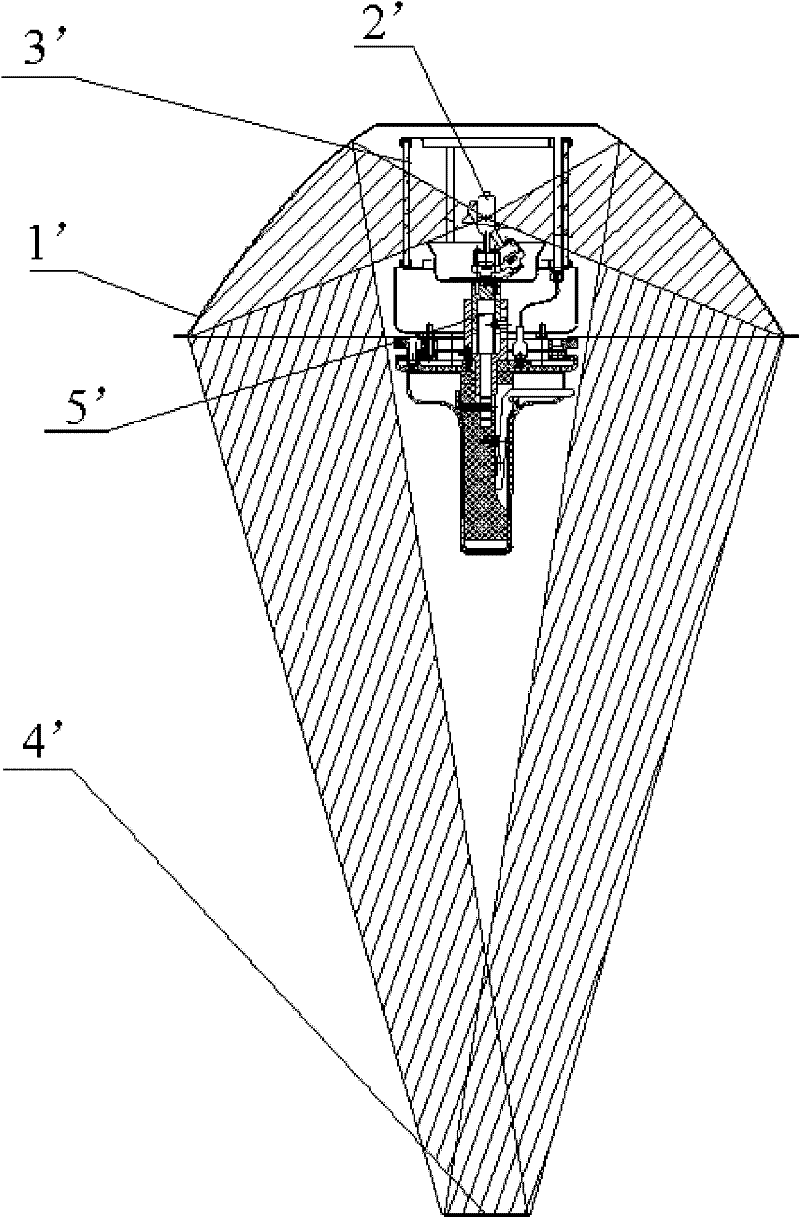
Since the illuminated surface 4' is the superposition of various light sources, the illumination depth is very poor
In addition, while the halogen bulb 2' emits visible light, it also emits infrared rays that greatly increase the temperature of the object, while the filter 3' can only filter out part of the infrared rays, and part of the infrared rays still reach the illuminated surface through the reflector 1' 4', resulting in an increase in temperature at 4' of the illuminated surface
When performing medical activities (surgery), it is necessary to lower the temperature of the wound site to prolong the survival of the wound tissue. However, the existing medical lighting equipment will inevitably cause the temperature of the 4' of the illuminated surface to rise, which will increase the temperature of the wound. , which would harm the patient
[0006] At the same time, using the figure 1 The medical lighting equipment with the structure shown in , since there is only one reflector 1' and one light source 2', all the illumination light is reflected from the light source 2' from one reflector 1', and the illuminated surface 4' of the reflector has only one , so that it cannot provide an ideal spatial area with consistent illuminance, color rendering index, and color temperature
[0007] in addition, figure 1 The reflector of the medical lighting equipment shown in the structure is very large, resulting in a large volume of the medical lighting equipment. When used for medical activity (lighting) lighting, it will prevent clean air from reaching the surgical wound site, and it is easy to damage the personnel involved in medical activities. (doctors performing surgical activities, etc.) causing injury

Method used


Image

  • Medical lighting device
  • Medical lighting device
  • Medical lighting device

Examples


Embodiment Construction

[0029] The embodiments of the present invention will be described in detail below in conjunction with the accompanying drawings, but the following embodiments and accompanying drawings are only used to understand the present invention, but not to limit the present invention. The present invention can be implemented in various ways defined and covered by the claims.

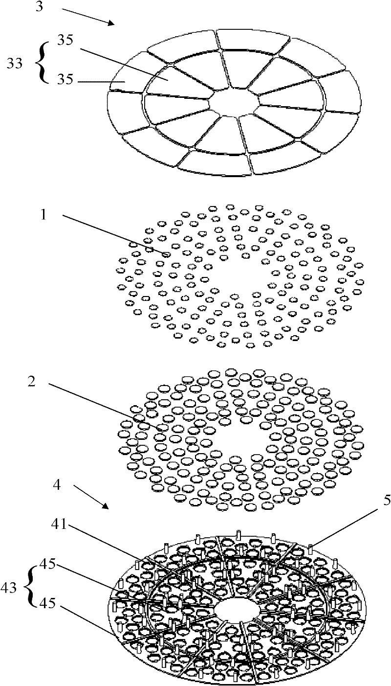
[0030] Such as figure 2 and image 3 As shown, in one embodiment of the present invention, the medical lighting device includes: a support frame, and a plurality of LED light sources 1 and a plurality of lenses 2 installed on the support frame, and a plurality of lenses 2 and a plurality of LED light sources 1 correspond to each other, and are installed in front of each corresponding LED light source, and multiple lenses gather the light emitted by multiple LED light sources toward the target position. The medical lighting device replaces traditional halogen bulbs with LEDs as the light source of medical lightin...


PUM


Abstract

The invention discloses a medical lighting device, comprising: a supporting frame; a plurality of LED light sources arranged on the supporting frame; The lens focuses the light emitted by the multiple LED light sources towards the target location. The medical lighting device improves the utilization rate of the light emitted by the light source, and provides a multi-layered illuminated surface and an ideal surgical lighting space. The optical path structure of medical lighting equipment is simplified, and the volume of medical lighting is reduced while satisfying the function of reducing the shadow of the illuminated object, making it easier for clean air to reach the surgical wound site, eliminating the need for participation in medical activities. Risk of injury to personnel (doctors performing surgical activities, etc.)

Description

technical field [0001] The invention relates to the field of medical lighting, in particular to a medical lighting device. Background technique [0002] In medical activities (surgery), the lighting requirements for medical lighting equipment are different from those for general lighting equipment. Medical lighting equipment must not only provide illumination for the area where medical activities (surgery) is being performed, but also have weakened light for irradiation The function of the shadow of the illuminated object produced by the illuminated object, and provide a three-dimensional area with consistent illuminance, color rendering index, and color temperature. [0003] In the existing medical lighting equipment used for medical activities (surgery), in order to project light onto the irradiation surface from different angles in this equipment, so as to achieve the effect of weakening the shadow, the light-emitting point is set on a spherical arc surface. The illumina...

Claims


Application Information

Patent Timeline
Patent Type & Authority Applications(China)
IPC IPC(8): F21S8/00F21V5/04F21V21/108F21W131/205F21Y101/02
Inventor 陆银发刘倩吴梁尹海文
Owner BEIJING AEONMED
Why Eureka
Try Eureka