The placement structure of the placement machine

A placement machine and placement technology, applied in the direction of assembling printed circuits with electrical components, can solve problems such as low efficiency, and achieve the effects of improving production efficiency, simplifying the placement process, and simple structure

Inactive Publication Date: 2011-12-07
SHENZHEN ETON AUTOMATION EQUIP
View PDF4 Cites 13 Cited by
  • Summary
  • Abstract
  • Description
  • Claims
  • Application Information

AI Technical Summary

Problems solved by technology

[0006] In view of the deficiencies of the prior art above, the purpose of the present invention is to provide a mounter structure to solve the problem of low efficiency of the mounter in the prior art when mounting large-size LED circuit boards

Method used


Image

  • The placement structure of the placement machine
  • The placement structure of the placement machine
  • The placement structure of the placement machine

Examples


Embodiment Construction

[0023] The invention provides a placement structure of a placement machine, which includes a placement head and a material tape reel used in conjunction with the placement head. In order to make the object, technical solution and effect of the present invention more clear and definite, the present invention will be further described in detail below with reference to the accompanying drawings and examples. It should be understood that the specific embodiments described here are only used to explain the present invention, not to limit the present invention.

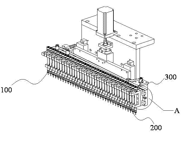
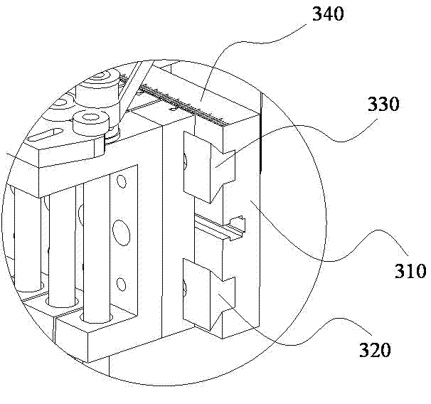
[0024] see figure 2 , figure 2 It is a schematic diagram of the placement head of the placement structure of the placement machine of the present invention. As shown in the figure, the placement head of the placement structure includes: at least 2 nozzle structures 100, nozzle bases 200 corresponding to the nozzle structures 100, and a first adjustment mechanism for adjusting the distance between the nozzle bases 200. ...


PUM


Abstract

The invention discloses a mounting structure of a mounter. The mounting structure of the mounter comprises a mounting head and a material band disc matched with the mounting head, wherein the mounting structure comprises at least two suction nozzle structures, suction nozzle bases corresponding to the suction nozzle structures and a first adjusting structure for adjusting distances among the suction nozzle bases; the suction nozzle structures are arranged on the suction nozzle bases; the suction nozzle bases are connected with the adjusting structure; the material band disc comprises material band holes for placing LED components and a second adjusting structure for adjusting distances among the material band holes; and the second adjusting structure is connected with the material band holes. With the adoption of the mounting structure of the mounter, the whole mounting process is simplified, the production efficiency is greatly increased and the requirement for large-scale and pipelining operating is satisfied. Meanwhile, the mounting structure of the mounter further has the advantages of simple structure, low cost and the like.

Description

technical field [0001] The invention relates to the technical field of electronic placement, in particular to a placement structure of a placement machine. Background technique [0002] The placement machine is also called "mounting machine" and "surface mount system". In the SMT production line, the mounter is generally configured after the dispenser or screen printing machine, and it is a device that accurately places surface mount components on the PCB pads through the mounting structure set on the mounter. . Existing placement machines mostly adopt fully automatic or semi-automatic mode. [0003] In the field of electronic placement technology, placement machines are widely used due to their advantages such as fast placement speed, accurate placement, low labor intensity, and stable quality. Most of the current placement machines use high-speed optical centering placement machines, and their structures are as follows: figure 1 As shown: the placement machine includes...

Claims


Application Information

Patent Timeline
Patent Type & Authority Applications(China)
IPC IPC(8): H05K3/30
Inventor 余耀国
Owner SHENZHEN ETON AUTOMATION EQUIP
Why Eureka
Try Eureka