Heavy-duty roll static pressure steady rest

A steady rest and static pressure technology, which is applied in the direction of grinding workpiece supports, grinding machines, metal processing equipment, etc., can solve problems such as large moment of inertia, heavy roll weight, and equipment damage, and achieve rapid start and stop, improved start-up ability, and stability The effect of support

Active Publication Date: 2011-12-14
HIECISE PRECISION EQUIP (KUNSHAN) CO LTD
View PDF9 Cites 6 Cited by
  • Summary
  • Abstract
  • Description
  • Claims
  • Application Information

AI Technical Summary

Problems solved by technology

[0005] Due to the heavy weight of the roll, the moment of inertia is quite large, so it is difficult to realize the quick start of the roll. After starting, if there is any problem in the grinding process of the roll or the grinding is over, it is difficult to realize the stop of the roll. During the grinding process, a lot of time will be wasted to achieve start and stop, and equipment damage will be caused due to the inability to stop quickly

Method used


Image

  • Heavy-duty roll static pressure steady rest
  • Heavy-duty roll static pressure steady rest
  • Heavy-duty roll static pressure steady rest

Examples


Embodiment

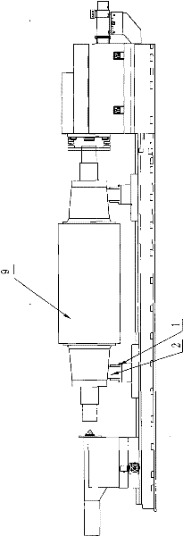
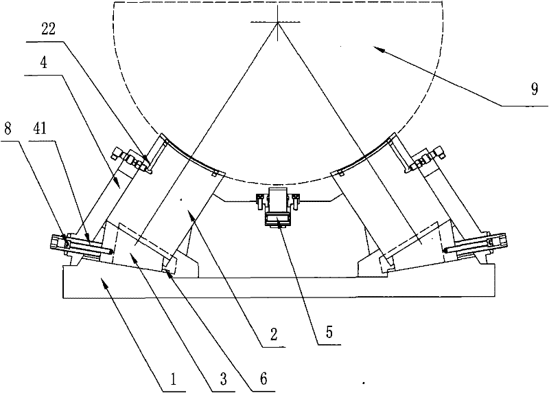
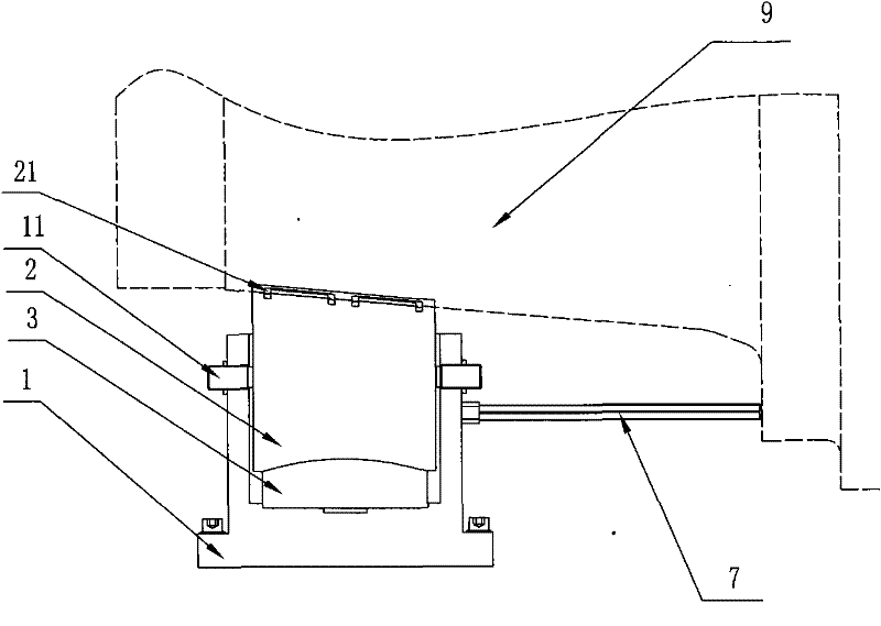
[0018] Embodiment: A heavy-duty roll static pressure center frame, including a static pressure center frame tile seat 1, a static pressure shoe 2, a wedge 3, a pressure plate 4 and a stop damping mechanism 5, based on the use direction, at least two static pressure The tiles 2 are inserted into the "U" groove of the static pressure center frame tile seat 1, each static pressure tile 2 is symmetrical along the axial vertical center plane of the static pressure center frame tile seat 1, and the upper end of the static pressure tile 2 is truncated Conical arc surface (matched with the outer conical surface of the roller 9 shaft shoulder), the truncated conical arc surface is provided with a concave static pressure oil groove 21, the lower end surface of the static pressure tile 2 and the upper end surface of the static pressure center frame tile seat 1 form a Trapezoidal space 6, the cross-sectional area of ​​the trapezoidal space 6 on the side away from the static pressure tile 2...


PUM


Abstract

The invention discloses a static pressure central frame of a heavy-duty mill roll. At least two static pressure tiles inserted into a 'U'-shaped slot of a tilting fillet of the static pressure central frame are symmetrical along the axial vertical central surfaces of the tilting fillet of the static pressure central frame. A concave static pressure oil groove is arranged on a truncated conical cambered surface at the upper ends of the static pressure tiles. A trapezoid space is formed between the lower end surfaces of the static pressure tiles and the upper end surface of the tilting fillet of the static pressure central frame. A wedge block can be just inserted into the trapezoid space. The depth of the wedge block in the trapezoid space in the inclined direction can be adjusted. Intersecting lines of the axial central surfaces of the static pressure tiles are collinear. The side wall of a pressing plate fixedly arranged on the tilting fillet of the static pressure central frame is tightly stuck with the back side walls of the static pressure tiles. A penetrating opening in the pressing plate is matched with the position of an oil supply port communicated with the static pressureoil groove. An oil cylinder barrel of a stop damping mechanism is fixedly located on the upper side surface of the tilting fillet of the static pressure central frame. A piston rod of an oil cylinderis fixedly connected with the lower end of a damping block. The piston rod of the oil cylinder can drive the damping block to move along the vertical direction. The static pressure central frame of the heavy-duty mill roll realizes quick starting and stopping of grinding of the mill roll.

Description

technical field [0001] The invention relates to an auxiliary mechanism of a roll grinder, in particular to a heavy-duty roll static pressure center frame. Background technique [0002] The bearing capacity of the static pressure steady frame of domestic CNC roll grinder manufacturing enterprises is 150 tons. To realize the ultra-heavy roll grinding process with a weight of 300 tons, two problems need to be solved: [0003] 1. On the premise of not causing any damage to the supporting surface (oil film bearing surface) of the roller, it can realize the support of the heavy roller; [0004] 2. After the support problem is solved, solve the start and stop of the heavy roller. [0005] Due to the heavy weight of the roll, the moment of inertia is quite large, so it is difficult to realize the quick start of the roll. After starting, if there is any problem in the grinding process of the roll or the grinding is over, it is difficult to realize the stop of the roll. During the g...

Claims


Application Information

Patent Timeline
Patent Type & Authority Applications(China)
IPC IPC(8): B24B5/37B24B41/06
Inventor 曹宇中赵泽明杜海涛王晓东姜大鹏徐宏伟雷邦昀
Owner HIECISE PRECISION EQUIP (KUNSHAN) CO LTD
Why Eureka
Try Eureka