Side-wall aeration ramp for free flow tunnel

A technology of aeration sills and tunnels, which is applied in the field of side wall aeration sills, can solve the problems that the gate cannot be partially opened, the side wall cavitation and cavitation, and the flow state of the water flow is poor, so as to improve the ventilation condition and increase the bottom area , Improve the effect of water flow

Inactive Publication Date: 2013-07-10
CHINA INST OF WATER RESOURCES & HYDROPOWER RES
View PDF6 Cites 0 Cited by
  • Summary
  • Abstract
  • Description
  • Claims
  • Application Information

AI Technical Summary

Problems solved by technology

[0007] The technical problem solved by the present invention is to provide a side wall aeration sill applied to open flow tunnels, which can effectively solve the problem of poor water flow, difficulty in aeration, and side wall problems after the pressure tunnel is connected to the open flow tunnel in the prior art. It is prone to cavitation cavitation and the problem that the gate cannot be partially opened and operated

Method used


Image

  • Side-wall aeration ramp for free flow tunnel
  • Side-wall aeration ramp for free flow tunnel
  • Side-wall aeration ramp for free flow tunnel

Examples


Embodiment 1

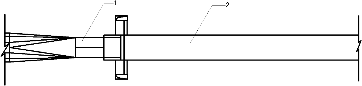
[0035] Such as Figure 5 As shown, the three-dimensional structure schematic diagram of the preferred embodiment 1 in the present invention; as Image 6 As shown, it is a schematic diagram of the top view structure of the preferred embodiment 1 in the present invention; as Figure 7 Shown is a schematic diagram of the side view structure of the preferred embodiment 1 of the present invention.

[0036] The side wall aeration sill of preferred embodiment 1 of the present invention is a pentahedron, and the structure of the pentahedron is divided into: upper surface 11, lower surface, left side 12, right side and back; wherein, upper surface 11 and lower surface All are right-angled trapezoids, and the length of the upper base in the upper surface 11 is B 1 , the length of the lower base is B 2 ; The left side 12 and the right side are right triangles, the length of the height in the left side 12 is H; the length of the height in the right side is H, and the length of the base...

Embodiment 2

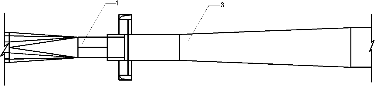
[0040] Such as Figure 8As shown, it is a schematic diagram of the three-dimensional structure of the preferred embodiment 2 of the present invention; as Figure 9 As shown, it is a schematic diagram of the top view structure of the preferred embodiment 2 in the present invention; as Figure 10 Shown is a side-view structural schematic view of the preferred embodiment 2 of the present invention.

[0041] The sidewall air-entrainment sill in the preferred embodiment 2 of the present invention is a combined structure of pentahedron and cuboid. The pentahedron is arranged on the front side of the cuboid. Wherein, the structure of the pentahedron is divided into: the upper surface 11, the lower surface, the left side 12, the right side and the back; wherein, the upper surface 11 and the lower surface are right-angled trapezoids, and the length of the upper base in the upper surface 11 is B 1 , the length of the lower base is B 2 ; The left side 12 and the right side are right...

Embodiment 3

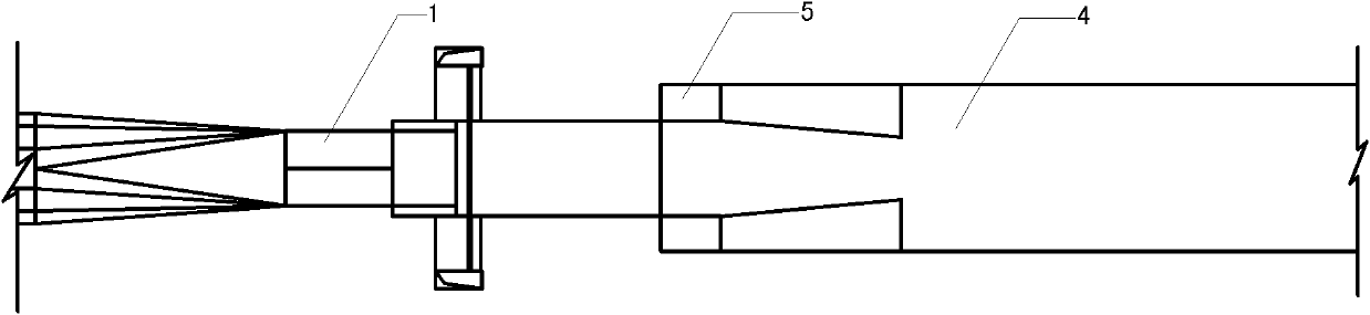
[0045] Figure 11 It is a schematic diagram of the three-dimensional structure of the third preferred embodiment of the present invention; Figure 12 It is a top view structure schematic diagram of preferred embodiment 3 in the present invention; Figure 13 It is a side view structural schematic diagram of the third preferred embodiment of the present invention.

[0046] The side wall aeration sill in preferred embodiment 3 of the present invention is a combined structure of pentahedron, cuboid and bottom plate. The pentahedron is arranged on the front side of the cuboid, and the combined structure of the pentahedron and the cuboid is arranged on the bottom plate. Wherein, the structure of the pentahedron is divided into: the upper surface 11, the lower surface, the left side 12, the right side and the back; wherein, the upper surface 11 and the lower surface are right-angled trapezoids, and the length of the upper base in the upper surface 11 is B 1 , the length of the lo...


PUM


Abstract

The invention discloses a side-wall aeration ramp applied in free flow tunnel, which is arranged on both sides of a start part of a free flow tunnel. The side-wall aeration ramp has a trapezoid contraction sudden enlargement shape; after an aeration ramp is suddenly enlarged or fallen, the aeration ramp is added, so that the linking problem that high speed water flow at the outlet of a spillway tunnel gate is converted from pressure flow to free flow can be solved properly, and an aeration effect of the water flow is enhanced and corrosion reduction and protection of aeration on the downstream high speed overflow surface are enhanced at the same time.

Description

technical field [0001] The invention relates to the field of flood discharge and energy dissipation in water conservancy projects, in particular to an aeration sill applied to a side wall of an open flow tunnel. Background technique [0002] In the transitional section from the pressure tunnel to the open flow tunnel, the flood discharge tunnel with high water head and low level generally adopts the connection type of sudden expansion and sudden drop of aeration sill in order to cooperate with the water-stop design of the gate. For the connection type of sudden expansion and sudden drop aeration sill, due to the high flow velocity at the gate outlet and the different front and rear widths, the transition process of water flow from pressure flow to open flow must be accompanied by drastic adjustment of hydraulic characteristics. The disadvantages of the connection type of sudden expansion and sudden drop aeration sills are: when the arc door is partially opened, the flow stat...

Claims


Application Information

Patent Timeline
Patent Type & Authority Patents(China)
IPC IPC(8): E02B8/06E02B3/10
Inventor 张东吴一红章晋雄刘之平张宏伟高建标张文远李长河项亚萍
Owner CHINA INST OF WATER RESOURCES & HYDROPOWER RES
Why Eureka
Try Eureka