
Combustible liquefied gas high-temperature hot blast furnace

A high-temperature hot blast stove, liquefied gas technology, applied in air heaters, fluid heaters, lighting and heating equipment, etc., can solve the problems of gas extinguishing, tea quality reduction, air pollution, etc., to achieve constant air temperature, heat utilization, etc. Fully and improve the effect of frying quality

Inactive Publication Date: 2013-08-14
浙江绿峰机械有限公司
View PDF10 Cites 0 Cited by
  • Summary
  • Abstract
  • Description
  • Claims
  • Application Information

AI Technical Summary

Problems solved by technology

Due to the unreasonable structural design of the high-temperature hot air stove in the prior art, it is difficult to stabilize the temperature and flow of the air outlet, resulting in a poor effect of drying and curing tea leaves, especially when the tea leaves are greened or the greening is not enough, the leaves are too green, or the greening is too much , the leaves are withered and yellow, these all bring a lot of troubles to the roasting of tea, and even reduce the quality of tea, affecting the income of tea farmers
Most of the existing high-temperature hot blast stoves use coal or firewood to obtain heat, and the smoke and dust generated are scattered everywhere, polluting the air, which is not environmentally friendly. The structural design of the gas-fired high-temperature hot blast stove is unreasonable, and there are potential safety hazards. When the natural wind enters the air, the gas is easily extinguished, causing gas leakage and causing accidents.

Method used


Image

  • Combustible liquefied gas high-temperature hot blast furnace
  • Combustible liquefied gas high-temperature hot blast furnace

Examples


Embodiment

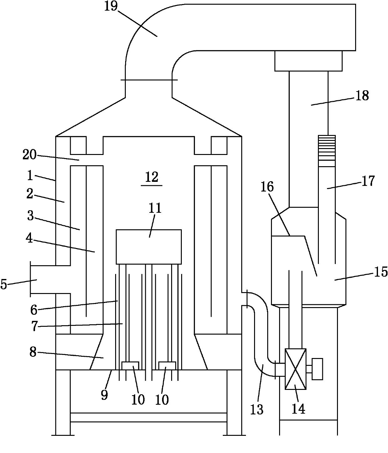
[0013] Example: see figure 1 with figure 2 The waste heat return duct 19 at the upper end of the combustion furnace 1 of the present invention is connected to the inner hot air chamber 4 of the combustion furnace 1, and then connected to the hot air outlet 5 through the outer hot air chamber 3, and the furnace 12 of the combustion furnace 1 passes through the hot air The tube 20 is connected to the hot air outlet chamber 2 of the combustion furnace 1, and the hot air outlet chamber 2 is connected to the hot air buffer chamber 15 through the air pipe 13 and the induced draft fan 14. The hot air buffer chamber 15 is provided with a buffer baffle 16, After the hot air is blocked, the temperature is uniform in the hot air buffer chamber 15 and then enters the waste heat return air duct 19 through the pipe 18. The hot air buffer chamber 15 is also provided with a decompression exhaust pipe 17 to balance the air pressure of the entire device; In the combustion chamber 8 of the combu...


PUM


Abstract

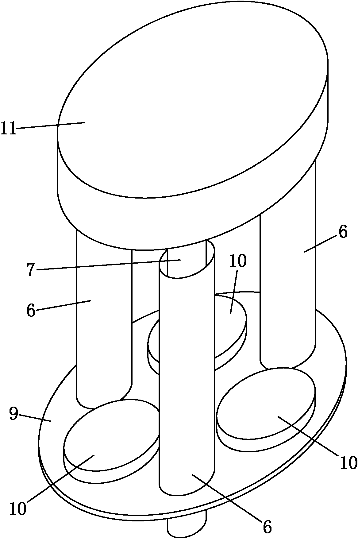
The invention discloses a combustible liquefied gas high-temperature hot blast furnace. The upper end of a combustion furnace is provided with a waste heat air return duct; the waste heat air return duct is communicated with an inner layer hot air chamber of the combustion furnace, and is communicated with a hot air outlet through an outer layer hot air chamber; a hearth of the combustion furnaceis communicated with a hot air outlet chamber of the combustion furnace; the hot air outlet chamber is communicated with a hot air buffer chamber through an air pipe and a draught fan; the hot air buffer chamber is communicated with the waste heat air return duct through a pipeline; in the combustion chamber of the combustion furnace, a plurality of liquefied gas combustion heads are uniformly distributed on a base plate, the base plate is provided with natural air inlet pipes at intervals of the liquefied gas combustion heads; and the bottom end of the air inlet pipe penetrates through the base plate and is open, and the top end of the air inlet pipe extends into and is suspended in the hearth of the combustion furnace. According to the invention, when the natural air inflows, the liquefied gas combustion heads can not be influenced, and accidents caused by the gas leakage due to gas extinguishing can be avoided; and a decompression exhaust pipe enables the pressure generated by the draught fan to be balanced, the liquefied gas combustion heads burn stably, the hearth temperature is constant, and the air outlet temperature of a hot air outlet is constant.

Description

Technical field [0001] The invention relates to a high-temperature hot blast stove, in particular to a high-temperature hot blast stove that burns liquefied gas. Background technique [0002] In the process of baking and curing tea, a high-temperature hot air stove is needed to provide hot air with constant temperature and flow. Due to the unreasonable structure design of the high-temperature hot-blast stove in the prior art, the outlet temperature and flow rate are difficult to stabilize, resulting in a poor effect of roasting and curing tea, especially when the tea is cured or is not cured enough, the leaves are too green, or the curing is excessive , The leaves are withered and yellow, all these bring a lot of troubles to the fried tea, and even reduce the quality of the tea and affect the income of tea farmers. Existing high-temperature hot air stoves mostly use coal or wood to obtain heat, and the smoke and dust generated are scattered everywhere, polluting the air, which i...

Claims


Application Information

Patent Timeline
Patent Type & Authority Patents(China)
IPC IPC(8): F24H3/02F24H9/18
Inventor 徐国华周强倪德江封雯
Owner 浙江绿峰机械有限公司
Learn More