Straw Compression Bundling Test Device and Test Method

A technology of compression molding and test device, which is applied in the direction of measuring device, testing of mechanical parts, testing of machine/structural parts, etc., which can solve the difficulty of changing the feeding amount, no retrieval, and difficulty in the pressure of the side plate and bottom plate of the compression chamber. Obtain and other problems, to achieve the effect of convenient operation, comprehensive detection and safe use

Inactive Publication Date: 2011-12-14
JIANGSU UNIV
View PDF8 Cites 15 Cited by
  • Summary
  • Abstract
  • Description
  • Claims
  • Application Information

AI Technical Summary

Problems solved by technology

[0003] 1. It is difficult to change the compression frequency, and it is difficult to obtain the compression effect under different compression frequencies
[0004] 2. The input torque of the transmission shaft is not easy to measure, and it is difficult to obtain the appropriate power required by the whole machine
[0005] 3. The compression force of the connecting rod is not easy to measure, and it is difficult to obtain the relationship between compression force and power consumption
[0006] 4. It is difficult to change the feeding amount, and it is difficult to obtain the influence of different feeding amounts on the quality of the bale
[0007] 5. During the compression process, the pressure on the side plate and bottom plate of the compression chamber is difficult to obtain
[0008] 6. The knotting mechanism cannot be tested separately
[0009] 7. It is not easy to observe the elastic-plastic deformation of the straw during the compression process in the field test
At present, only the related patents of the mechanical square baler knotter (CN201450886U) and the square baler (CN101138293) can be retrieved, while the relevant patents related to the detection of the performance and components of the baler can eliminate field factors not yet retrieved

Method used


Image

  • Straw Compression Bundling Test Device and Test Method
  • Straw Compression Bundling Test Device and Test Method
  • Straw Compression Bundling Test Device and Test Method

Examples


Embodiment Construction

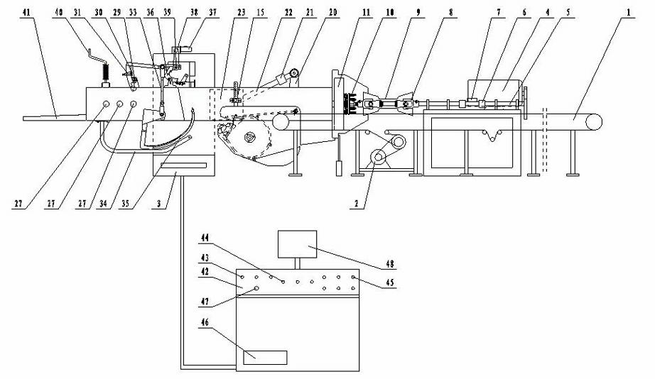
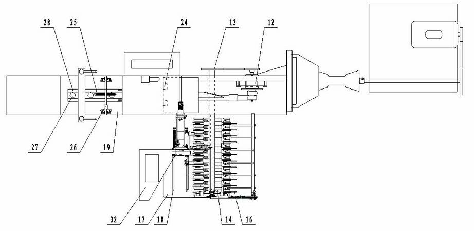
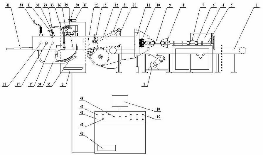
[0026] Such as figure 1 , 2 As shown, it mainly includes material conveying device, packing compression device, binding device and detection and control device. The conveying device includes a conveyer belt driving motor 2, a conveyer belt 1 and a tensioning wheel. During the test, the rotating speed of the motor 2 can be adjusted according to the required feeding amount. The packing compression device includes a frame and a base 3, connected to the power input shaft 5 of the driving motor 4, and a speed-torque sensor 7 is installed on the power input shaft 5, and the transmission torque and the change of the speed are measured during the test. The power input shaft 5 is connected to the main gear box 12, and the main gear box 12 is connected to the pick-up device driving wheel 13 on one side, and the height of the pick-up device can be adjusted by the pick-up device height adjusting device 15; the main gear box 12 is connected to the crank 20 and the connecting rod 22, Ins...


PUM


Abstract

The invention discloses a straw compression forming and bundling test method which comprises a material conveying device, a filler compression device, a bundling device and a detection and control device and can be used for simulating the working conditions of a straw baling press in the field and reproducing processes of picking up, compressing and bundling during straw collection. The method comprises the following steps of: obtaining different feeding quantities by changing the layer thickness of materials on a conveying belt and the speed of the conveying belt; obtaining different compression frequencies by adjusting the rotation speed of a transmission shaft and analyzing the influence of the compression frequencies on the straw bundle quality; obtaining different compression forces by adjusting inclination angles of a press plate on a compression chamber and analyzing the influence of the compression forces on the straw bundle density and the buckling rate; and obtaining the elasticity and plasticity deformation simulation of the straws in the compression process by utilizing high-speed photography. The test device and method disclosed by the invention has the advantages of use safety, detection completeness, convenience for operation and capabilities of eliminating the defects of the traditional field test method and obtaining more detailed and scientific information.

Description

technical field [0001] The invention relates to the technical field of straw bundling test devices, in particular to a straw compression molding bundling test device. Background technique [0002] The collection, storage and transportation of crop straws has always been the primary problem restricting the industrial scale utilization of agricultural biomass resources. The development and development of balers is one of the effective ways to solve the problem of agricultural biomass straw collection, storage and transportation, and meet the industrialized utilization. At present, the research and improvement of each part of the baler mainly depends on the field test of the prototype, but the field test is affected by the climate, field conditions and the limitations of the adjustable range of the parameters of the machine itself, which makes this test method have many limitations. Certain metrics cannot be measured in real time. Mainly manifested in the following aspects: ...

Claims


Application Information

Patent Timeline
IPC IPC(8): G01M13/00G01M99/00
Inventor 李耀明徐立章尹建军徐剑
Owner JIANGSU UNIV
Why Eureka
Try Eureka