
Electrowetting display device based on photoluminescence effect

An electrowetting display and photoluminescence technology, which is applied in the direction of optics, optical components, static indicators, etc., can solve the problems of poor display effect of electrowetting display devices, and achieve bright colors, bright colors, and high brightness. Effect

Inactive Publication Date: 2011-12-14
陈明晖
View PDF2 Cites 16 Cited by
  • Summary
  • Abstract
  • Description
  • Claims
  • Application Information

AI Technical Summary

Problems solved by technology

[0008] The technical problem solved by the present invention is to construct an electrowetting display device based on the photoluminescence effect, and overcome the technical problem of poor display effect of the electrowetting display device in the current technology

Method used


Image

  • Electrowetting display device based on photoluminescence effect
  • Electrowetting display device based on photoluminescence effect
  • Electrowetting display device based on photoluminescence effect

Examples


Embodiment Construction

[0031] The technical solutions of the present invention will be further described below in conjunction with specific embodiments.

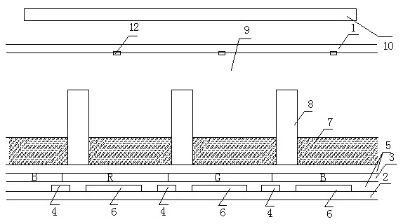
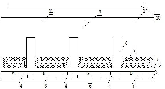
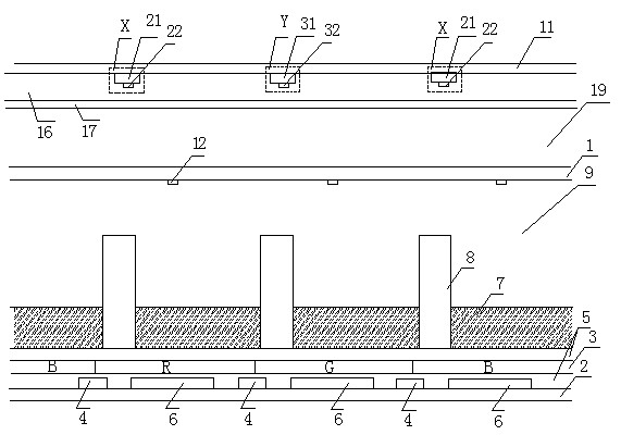
[0032] Such as figure 1 As shown, the specific embodiment of the present invention is: the electrowetting display device based on the photoluminescence effect of the present invention includes a first substrate 1, a second substrate 2 opposite to the first substrate 1, a first fluid 7, The second fluid 9, the partition wall 8 and the common electrode 12 arranged on the first substrate 1, one or more hydrophobic insulating layers 5, a plurality of TFT switches 4 arranged in a matrix on the second substrate 2 and There are a plurality of electrodes 6, there are gaps between the adjacent electrodes 6, and the partition wall 8 is arranged on the hydrophobic insulating layer 5 in grid form corresponding to the gaps to define pixel units, and the hydrophobic insulating layer 5 is arranged on the second Between a fluid 7 and the plurality of TFT switche...


PUM


Abstract

The present invention relates to an electrowetting display device based on the photoluminescence effect. By arranging the fluorescent layer or the hydrophobic insulating fluorescent layer between the second substrate and the first fluid, ultraviolet light, purple light or blue light can After the fluorescent layer is irradiated, a photoluminescent effect occurs to form actively luminescent color graphics, which makes the electrowetting display device have high brightness, brighter colors and more vivid colors.

Description

technical field [0001] The present invention relates to an electrowetting display device, in particular to an electrowetting display device based on photoluminescence effect. Background technique [0002] Electrowetting display is a new technology in recent years, which has attracted much attention because of its low power consumption and high response speed. At present, color electrowetting displays are the key direction of research and development. There are three main types of color electrowetting displays in the existing technology, namely: [0003] The first is the pre-color filter method. A color filter is arranged on the first substrate of the display screen, and the color filter includes a plurality of RGB sub-pixels distributed in a matrix, and each sub-pixel corresponds to a transparent electrode. The surface of the color filter may be provided with a transparent common electrode. [0004] The second is the color filter method of coloring layer. For example...

Claims


Application Information

Patent Timeline
Patent Type & Authority Applications(China)
IPC IPC(8): G02B26/02G09G3/34
Inventor 陈明晖
Owner 陈明晖
Learn More