Liquid crystal lens and 3D display device

A liquid crystal lens and display device technology, which is applied in the directions of lenses, static indicators, optics, etc., can solve the problems of not being able to use in the field of naked-eye 3D display, the focal length of the cylindrical lens is not adjustable, and it is difficult to play 2D image switching.

Inactive Publication Date: 2011-12-14
SHENZHEN CHINA STAR OPTOELECTRONICS TECH CO LTD
View PDF2 Cites 17 Cited by
  • Summary
  • Abstract
  • Description
  • Claims
  • Application Information

AI Technical Summary

Problems solved by technology

However, the focal lengths of the lenticular lens and the self-focusing lens are not adjustable. At the same time, if the 3D display device using this lens does not use other additional devices, it is difficult to switch between playing 2D images.
Therefore, the existing lenses can no longer satisfy the use in the field of naked-eye 3D display to a certain extent.

Method used


Image

  • Liquid crystal lens and 3D display device
  • Liquid crystal lens and 3D display device
  • Liquid crystal lens and 3D display device

Examples


Embodiment 1

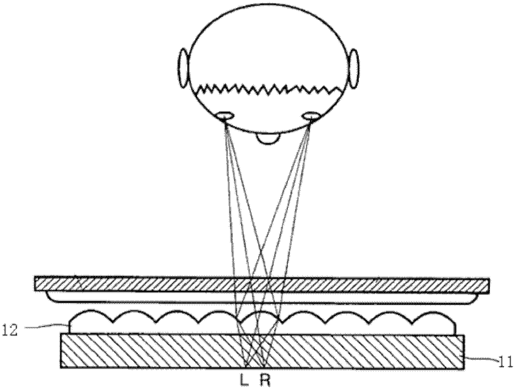
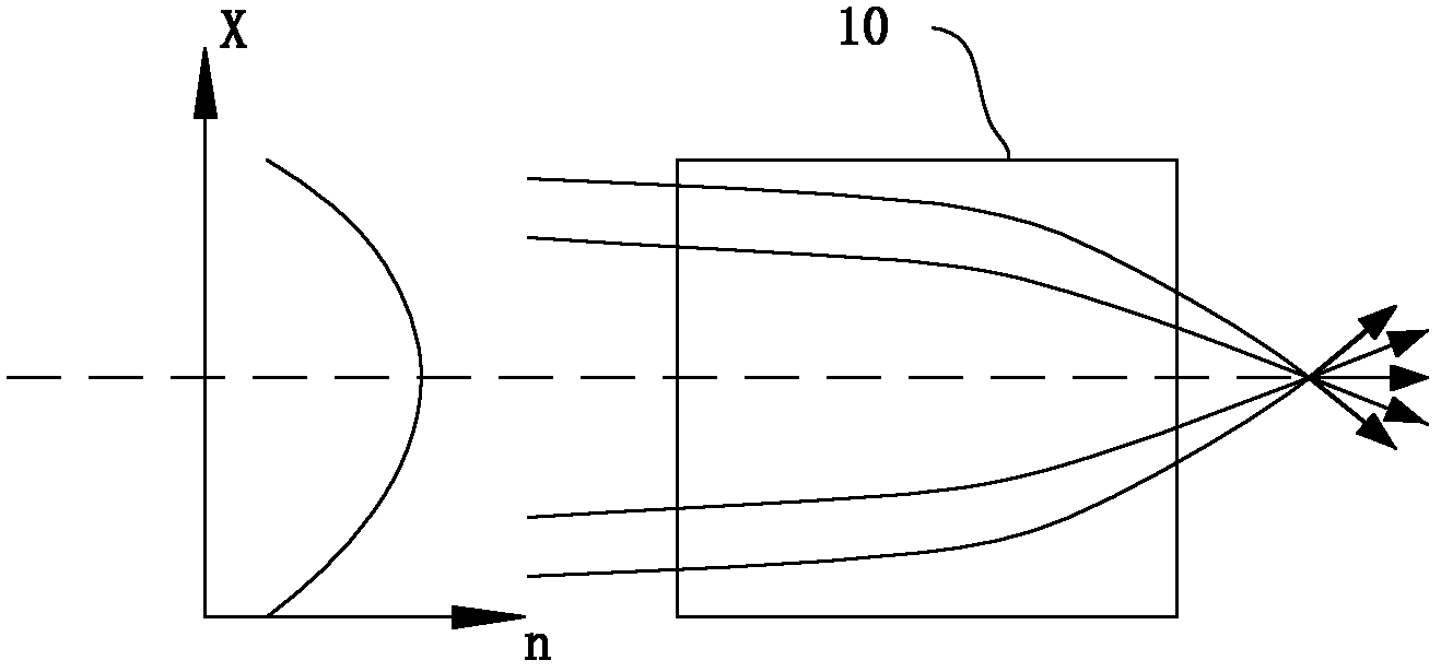
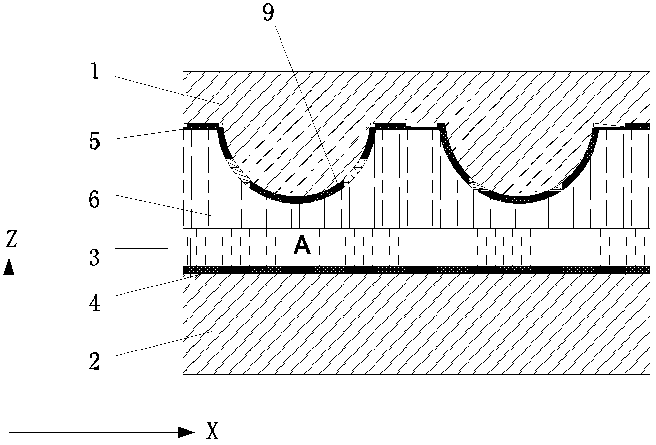
[0035] A liquid crystal display device capable of naked-eye 3D display includes a liquid crystal panel and a liquid crystal lens arranged in front of the liquid crystal panel. The structure of the first embodiment of the liquid crystal lens is as follows: image 3 As shown, the counter electrode 5 of the liquid crystal lens on the upper substrate 1 has a plurality of concave curved surface structures 9 with the same shape and arranged in parallel to make the distance between the electrode and the counter electrode smaller. The vertices are symmetrical and can be in a hemispherical structure; correspondingly, the side of the upper substrate 1 corresponding to the counter electrode 5 has a protruding area with the same structure as the concave curved surface structure 9 . The thickness of the liquid crystal layer is uniform, and an insulating layer 6 is filled between the liquid crystal layer and the protruding counter electrode 5 , so that the counter electrode 5 is insulated fr...

Embodiment 2

[0040] The structure of the liquid crystal lens of the second embodiment is similar to that of the first embodiment, and the difference from the first embodiment is that, as Figure 5 As shown, the electrode 4 of the lower substrate 2 is designed to have a concave curved surface structure 9 that makes the distance between the electrode and the counter electrode smaller. Correspondingly, the side of the lower substrate 2 corresponding to the electrode 4 has a concave surface The convex regions of the curved surface structure 9 are likewise configured. The thickness of the liquid crystal layer is uniform, and an insulating layer 6 is filled between the liquid crystal layer and the protruding electrode 4 , so that the electrode 4 is insulated from the liquid crystal layer 3 . The upper substrate 2 and the counter electrode 5 on it are arranged in a plane, and the liquid crystal adopts a vertical alignment type negative nematic liquid crystal (Negative Nematic LC). The liquid crys...


PUM


Abstract

Provided are a liquid crystal lens and a 3D display device. The liquid crystal lens comprises: a lower layer substrate (2) disposed with an electrode (4) and an upper layer substrate (1) disposed with a counter electrode (5) arranged opposite each other, the electrode (4) and the counter electrode (5) being insulated from each other to form an electrical field; and a liquid crystal layer (3) disposed between the lower layer substrate (2) and the upper layer substrate (1), the liquid crystal being vertically oriented nematic liquid crystal. The electrode (4) on the lower layer substrate (2) or the counter electrode (5) on the upper layer substrate (1) has a concave curved surface structure for decreasing the spacing between the electrode (4) and the counter electrode (5). As the liquid crystal lens has the concave curved surface structure (9) for decreasing the spacing between the electrode (4) and the counter electrode (5), the field intensity in the electrical field has gradient changes, and the angles at which the liquid crystal molecules in the liquid crystal layer (3) tilt under the effect of the electrical field also have gradient changes, so that the refraction rate of the liquid crystal layer (3) has gradient changes, thereby forming a liquid crystal lens with the refraction rate changing in gradient, which is applicable to a liquid crystal display to achieve a 3D display effect.

Description

technical field [0001] The invention relates to the fields of lenses and naked-eye 3D displays, and more specifically, to a liquid crystal lens and a 3D display device. Background technique [0002] Existing lenses are all ordinary optical lenses, and their focal lengths are often fixed, which limits the application of lenses in many fields. Take the naked-eye 3D display field as an example. Refracted to the corresponding viewing position of the left and right eyes, it is common to use a lenticular lens to match the refractive index of the light path, such as figure 1 As shown in , its principle is to add a layer of lenticular lens 12 in front of the display screen 11, so that the image plane of the display screen 11 is located on the focal plane of the lens, and the pixels of the image below each lenticular lens 2 are divided into several sub- Pixels, so that the lens can project each sub-pixel in different directions, so when the eyes watch the display screen from differe...

Claims


Application Information

Patent Timeline
Patent Type & Authority Applications(China)
IPC IPC(8): G02F1/29G02F1/1343G02F1/1337G02F1/133G02B27/22
CPCG02B27/22H04N2013/0081H04N13/0242H04N13/04G02F1/29G02F2001/294G02F1/13G02B3/0087G02F1/133371G02B3/12G02F1/294H04N13/243
Inventor 康志聪
Owner SHENZHEN CHINA STAR OPTOELECTRONICS TECH CO LTD
Why Eureka
Try Eureka