Contactless power supply device

A non-contact power supply and circuit technology, which is applied in the direction of circuit devices, circuits, inductors, etc., can solve the problems of thick coils, difficulty in configuration, and increased weight, and achieve the effects of thinner coils, easier configuration, and lighter weight

Inactive Publication Date: 2011-12-14
SHOWA AIRCRAFT INDUSTRY
View PDF7 Cites 25 Cited by
  • Summary
  • Abstract
  • Description
  • Claims
  • Application Information

AI Technical Summary

Problems solved by technology

However, the non-contact power supply device 17 is pointed out to have the following problem: Even if it has such a flat structure, since the power transmission coil 3 and the resonant coil 16, and the power receiving coil 8 and the resonant coil 16 are in the positional relationship of overlapping in the magnetic circuit , the result is that the overall coil thickness is thick
[0019] In addition, on the vehicle B side, for example, its floor side, since the resonant coil 16 of the non-contact power supply device 17 of the prior application is overlapped and arranged in the magnetic circuit leading to the power receiving coil 8, correspondingly, for connecting the two coils 8 , 16 The space for installation under the floor surface increases, and the weight also increases
Therefore, it is pointed out that the non-contact power supply device 17 of this prior application is not easy to arrange on the vehicle B side or the like

Method used


Image

  • Contactless power supply device
  • Contactless power supply device
  • Contactless power supply device

Examples


Embodiment

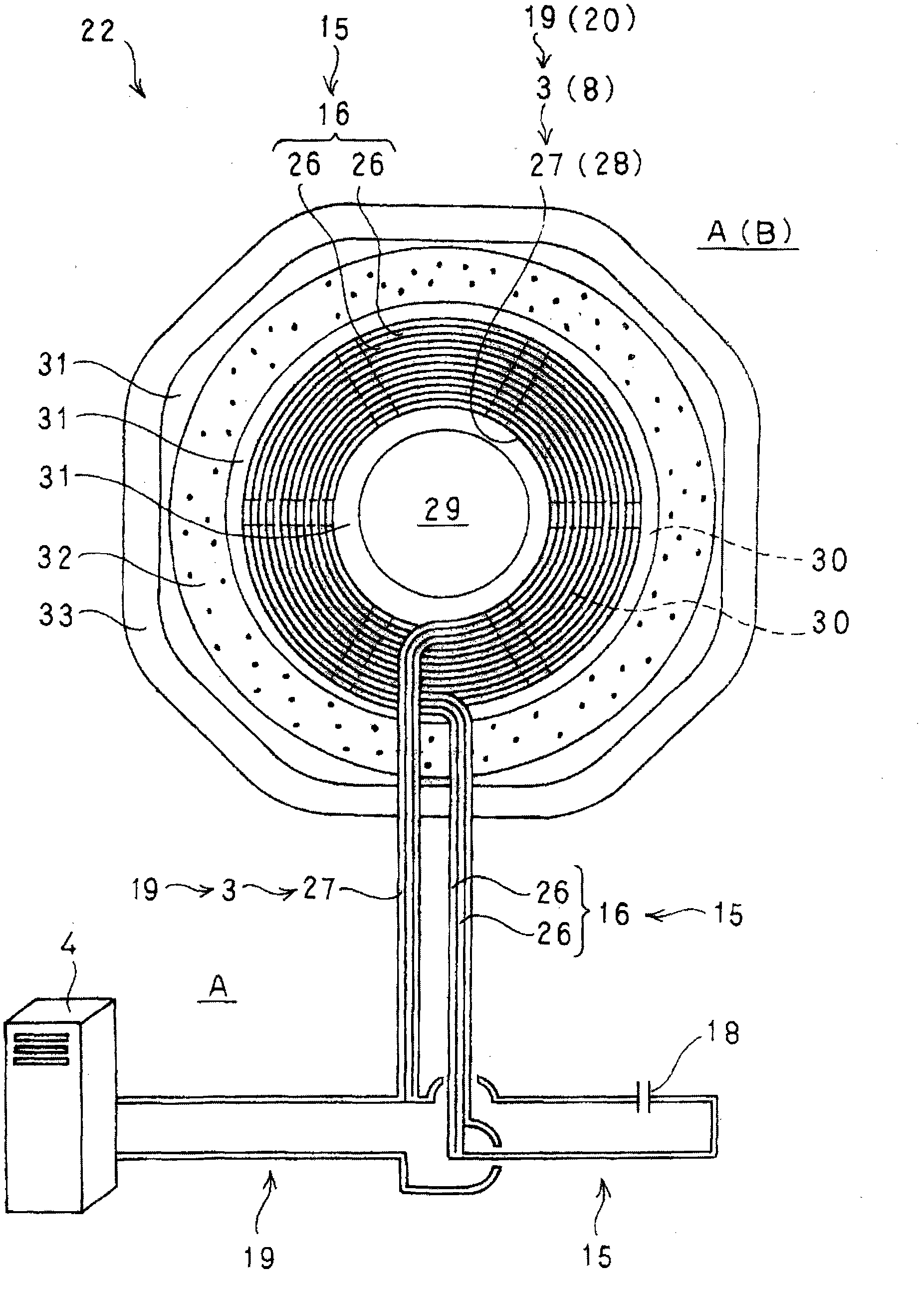
[0130] Here, an embodiment of the present invention will be described.

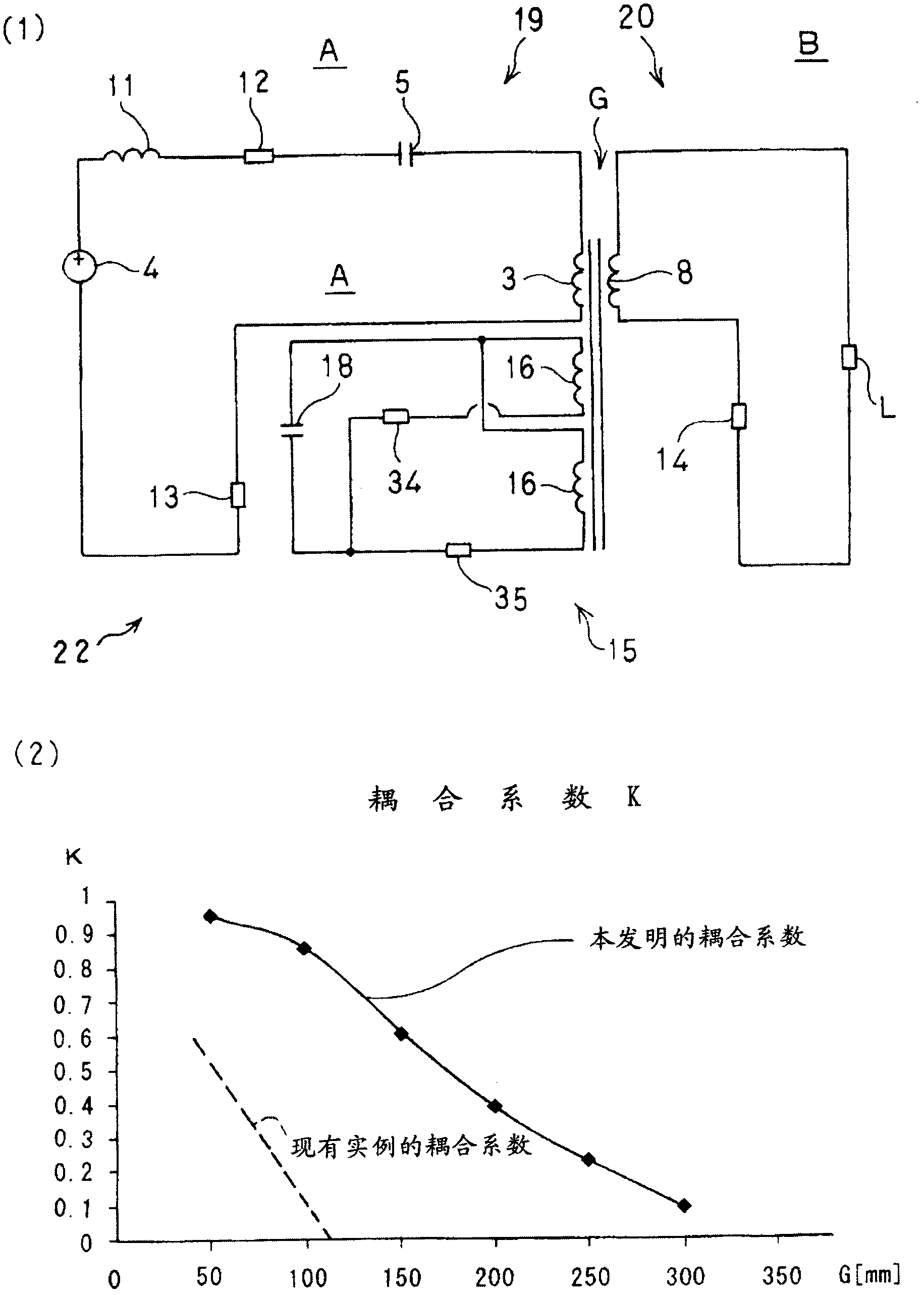
[0131] figure 2 (2) is for figure 2 (1) The embodiment of the non-contact power supply device 22 of the present invention shown and Figure 4 (1) Graphs of respective coupling coefficient data of the conventional example non-contact power supply apparatus 1 shown.

[0132] Comparing the experimental data with this graph also proves that the non-contact power supply device 22 of the present invention has a better coupling coefficient indicating the degree of electromagnetic coupling between the magnetic circuit coils than the conventional non-contact power supply device 1 . The experimental data is obtained by calculating the coupling coefficient K for each interval size based on actual measurement values ​​while changing the interval size of the air gap G for the contactless power supply device 22 and the contactless power supply device 1 .

[0133] According to the obtained experimental data, the co...


PUM


Abstract

In a non-contact power feeding device 22 of the present invention, power is fed through an air gap G with no contact from a power transmission coil 3 of a power feeding side circuit 19 to a power receiving coil 8 of a power receiving side circuit 20, which are located to face each other, based on a mutual induction effect of electromagnetic induction. In such a non-contact power feeding device 22, a resonant coil 16 of a repeating circuit 15 is disposed on the power transmission coil 3 side and / or the power receiving coil 8 side. The resonant coil 16 is wound in parallel on the same plane as the power transmission coil 3 and / or the power receiving coil 8. The resonant coil 16, the power transmission coil 3 and the power receiving coil 8 are respectively composed of a single insulated conducting wire or a number of insulated conducting wires.

Description

technical field [0001] The present invention relates to a non-contact power supply device. That is, the present invention relates to a non-contact power supply device that supplies electric power in a non-contact state from a power transmission side fixedly arranged on the ground side to a power reception side mounted on a vehicle or the like. Background technique [0002] A non-contact power supply device for externally supplying electric power to, for example, a storage battery of an electric vehicle without mechanical contact such as a cable has been developed and put into practical use as required. [0003] This non-contact power supply device is based on the mutual inductance of electromagnetic induction, and there is an air gap ranging from tens of millimeters to hundreds of millimeters from the power transmission coil fixed on the ground to the power reception coil mounted on electric vehicles or other vehicles. ) while performing position correspondence while supply...

Claims


Application Information

Patent Timeline
Patent Type & Authority Applications(China)
IPC IPC(8): H02J17/00B60L5/00H01F38/14
CPCY02T90/14Y02T90/122Y02T10/7088Y02T10/7005B60L11/182B60L53/12B60L53/122B60L2200/26Y02T10/70Y02T10/7072H01F38/14H02J50/12Y02T90/12
Inventor 山本喜多男佐藤刚阿部馨介望月正志冲米田恭之
Owner SHOWA AIRCRAFT INDUSTRY
Why Eureka
Try Eureka