
a heating wire

A heating wire and heating material technology, applied in the field of heating wire, can solve the problems of affecting oil flow, obstructing oil passage, oil height, etc., to achieve the effect of saving electric energy, ensuring heating effect, and reducing heating speed

Active Publication Date: 2011-12-14
山东宇升电子科技有限公司
View PDF4 Cites 2 Cited by
  • Summary
  • Abstract
  • Description
  • Claims
  • Application Information

AI Technical Summary

Problems solved by technology

[0002] At present, the heating of diesel filter cups is generally heated by heating wires. Whether the heating wires are inside the filter cup or in the internal pipeline passage of the filter cup, the internal heating wire structure is the same. This structure makes the heating in the internal pipeline passage of the filter cup The hot wire is also generating a lot of heat, so that the temperature of the oil in the internal pipeline passage of the filter cup is too high, which is prone to gasification and hinders the oil passage, and the outer diameter of the heating wire is too thick relative to the internal pipeline passage of the filter cup, which affects the oil flow

Method used


Image

  • a heating wire
  • a heating wire
  • a heating wire

Examples


Embodiment 1

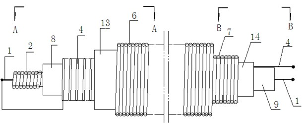
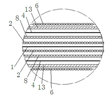
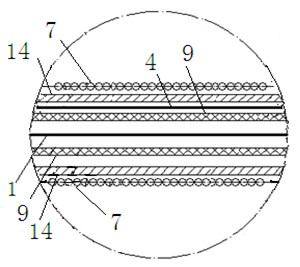
[0024] In the heating wire of this embodiment, the hollow of the first insulating layer 3 is wrapped with a loop line 1, and the outer layer of the first insulating layer 3 is wrapped with a coiled first heating material layer 4, and the first heating material layer 4 is connected with the loop line. The top of 1 is connected to form a loop, the outer layer of the first heating material layer 4 is covered with a second insulating layer 5, and the outer layer of the second insulating layer 5 is covered with a second protective spring, which is divided into a second protective spring. The thick section 6 of the dense spring is different from the thin section 7 of the second protective dense spring. The structure of the first heating material layer 4 corresponding to the package in the position of the thin section 7 of the second protective dense spring is linear. When in use, the second protective tight The thick spring section 6 is located inside the filter cup 11 to fully heat ...

Embodiment 2

[0033] A heating wire of this embodiment differs from Embodiment 1 in that

[0034] The part of the first insulating layer 3 inside the filter cup is equipped with a first protective spring 2 in its hollow, and the circuit line 1 passes through the middle of the first protective spring 2 .

[0035] Beneficial effect:

[0036] Since the first protective spring 2 is installed inside the first insulating layer 3 in the filter cup, the circuit line 1 has a certain space in the first insulating layer 3, which can disperse part of the heat of the circuit line, so that the first insulating layer 3 will not Accelerated aging due to high temperature; at the same time, it can ensure that the circuit line passes through the center of the first insulating layer 3, so the heating line is safer and less likely to be damaged.


PUM


Abstract

The invention relates to a heating wire and belongs to the field of heating wire structures. The heating wire is characterized in that: a loop wire (1) is covered in a hollow of a first insulation layer (3); a first coiled heating material layer (4) is covered on an outer layer of the first insulation layer (3) and connected with the top end of the loop wire (1) to form a loop; a second insulation layer (5) is covered on an outer layer of the first heating material layer (4); a second protection seal spring is covered on an outer layer of the second insulation layer (5); the second protectionseal spring is divided into a second protection seal spring thick section (6) and a second protection seal spring thin section (7) which have different thicknesses; and the first heating material layer (4) correspondingly covered in the second protection seal spring thin section (7) has a straight structure. When the heating wire is used, the thick section is arranged in a filter cup, and the thin section is arranged in a pipe passage in the filter cup; and the heating material layer in the filter cup has a coiled structure and the heating material layer in the pipe passage in the filter cup has the straight structure, so the energy consumption can be reduced, and the heating wire can meet the requirements for saving energy and reducing emission.

Description

technical field [0001] The invention relates to a heating wire, specifically a special wire for heating a diesel filter cup, and belongs to the technical field of heating wire structure. Background technique [0002] At present, the heating of diesel filter cups is generally heated by heating wires. Whether the heating wires are inside the filter cup or in the internal pipeline passage of the filter cup, the internal heating wire structure is the same. This structure makes the heating in the internal pipeline passage of the filter cup The hot wire is also generating a lot of heat, so that the temperature of the oil in the internal pipeline passage of the filter cup is too high, which is prone to gasification and hinders the oil passage, and the outer diameter of the heating wire is too thick relative to the internal pipeline passage of the filter cup, which affects the oil flow. Contents of the invention [0003] The purpose of the present invention is to solve the shortco...

Claims


Application Information

Patent Timeline
Patent Type & Authority Applications(China)
IPC IPC(8): H05B3/56
Inventor 孙靖茗
Owner 山东宇升电子科技有限公司
Learn More