
a scrubber

A gas scrubber and gas scrubbing technology, applied in the field of gas scrubbers, can solve problems such as difficult sewage outlets, discharge, easy slag accumulation at the bottom of the tower, etc., and achieve the effect of long residence time

Active Publication Date: 2011-12-21
FUJIAN BOYI ENVIRONMENTAL PROTECTION TECH
View PDF4 Cites 2 Cited by
  • Summary
  • Abstract
  • Description
  • Claims
  • Application Information

AI Technical Summary

Problems solved by technology

At present, when the gas scrubber is dealing with high-dust gas, there are dead angles, which lead to dust accumulation, especially affecting the smoothness of the air intake, and the bottom of the tower is also prone to slag accumulation, which is difficult to discharge from the sewage outlet. After a certain working cycle, the slag needs to be cleaned Processing, causing inconvenience to the link operation

Method used


Image

  • a scrubber
  • a scrubber

Examples


Embodiment Construction

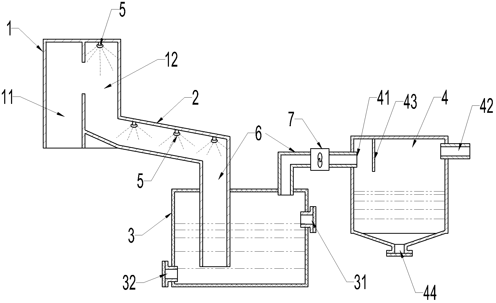
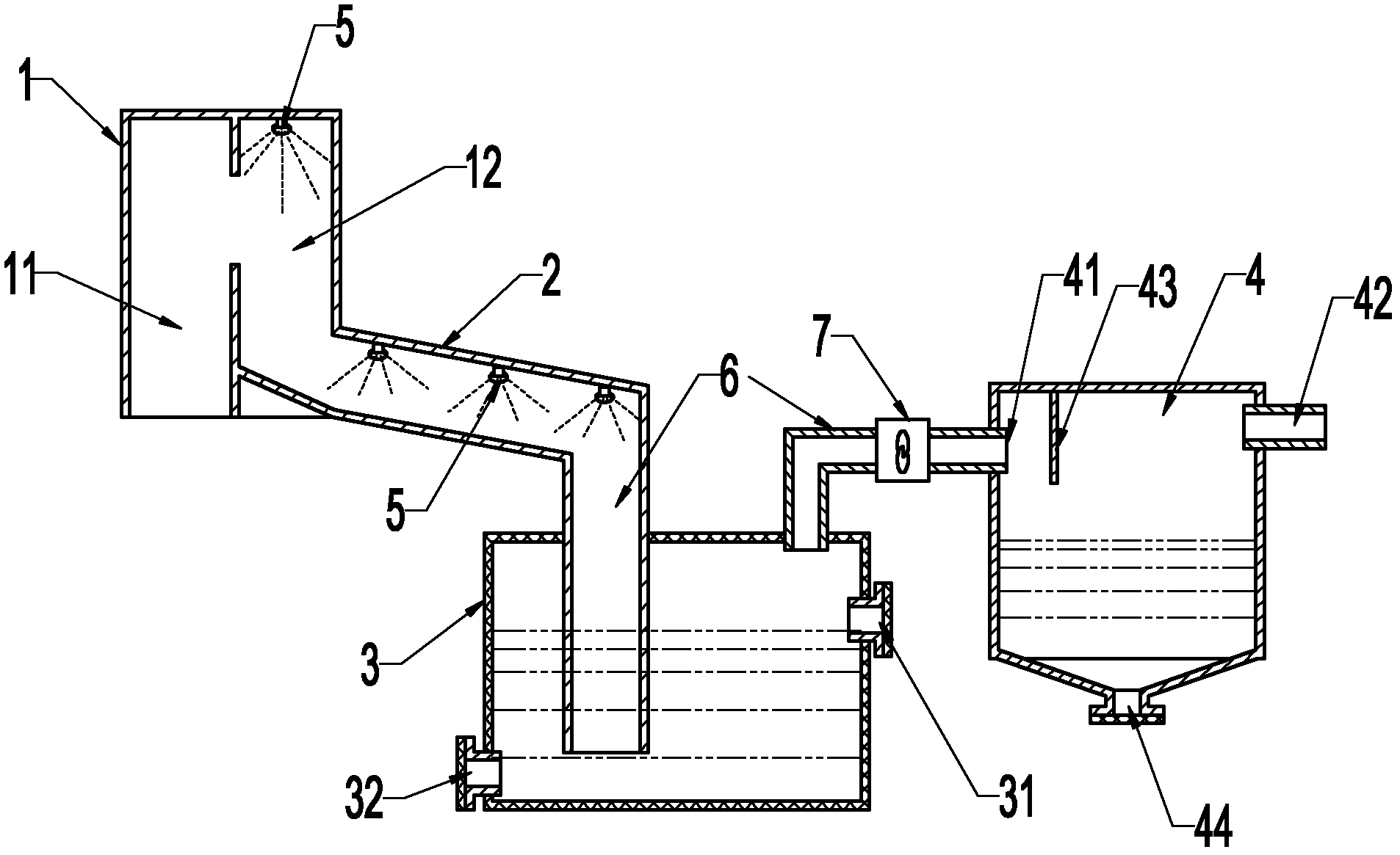
[0018] refer to figure 1 , the gas scrubber includes a vertical tower 1, a horizontal tower 2, a scrubber chamber 3 and an oil-gas separation chamber 4; connected to each other, so that the incoming gas can be fully sprayed, without pipe dead ends, without dust accumulation, the top of the spray chamber 12 is equipped with a sprinkler head 5; the horizontal tower 2 is connected with the bottom of the spray chamber 12, in order to make the Quickly discharge accumulated water, etc., the bottom of the spray chamber 12 is an inclined structure, which is inclined towards the direction of the horizontal tower 2, and the bottom of the horizontal tower 2 itself is at least an inclined structure. The end connected to the spray chamber 12 is high, and the end connected to the pipeline 6 is low. , the high-speed flowing water can quickly take away all kinds of dust, and achieve maintenance-free tower;

[0019] The gas washing chamber 3 is a closed body, the pipeline 6 introduced from th...


PUM


Abstract

The invention relates to a scrubber tower. The scrubber tower is characterized by comprising a vertical tower, a transverse tower, a scrubbing chamber and an oil-gas separation chamber, wherein the vertical tower is longitudinally separated into a gas inlet chamber and a spray chamber, the gas inlet chamber is communicated with the middle part of the spray chamber, and a spray head is arranged onthe top of the spray chamber; the transverse tower is communicated with the bottom of the spray chamber, and spray heads are distributed on the top of the transverse tower; a pipeline communicated with the end part of the transverse tower is inserted to a position below the liquid level of the scrubbing chamber, the top of the scrubbing chamber is connected with a draught fan through a pipeline, and output of the draught fan is communicated with an air inlet on the upper part of the oil-gas separation chamber through a pipeline; an air outlet is also formed on the upper part of the oil gas separation chamber; and an oil separation baffle is arranged between the air inlet and the air outlet, and close to the side of the air inlet. According to the scrubber tower, a structure of the vertical and the transverse towers is adopted and is matched with the scrubbing chamber and the oil-gas separation chamber, so that the aim of purifying a gas source is achieved.

Description

Technical field: [0001] The invention relates to a gas scrubber matched with a gas generator, and is especially suitable for the harmless treatment of exhaust gas from gas generators, garbage cracking furnaces and incinerators. Background technique: [0002] Gas scrubbers, as the name suggests, are used to wash gas, whether it is dust removal, cooling or harmless treatment, except for the difference in washing liquid, its structure is roughly the same. The main body is a vertical tower, the air inlet and the exhaust port are respectively set at the lower part and the top of the vertical tower, the upper part of the vertical tower is provided with a spray head, and the bottom of the tower is provided with necessary sewage outlets. At present, when the gas scrubber is dealing with high-dust gas, there are dead angles, which lead to dust accumulation, especially affecting the smooth intake, and the bottom of the tower is also easy to accumulate slag, which is not easy to discha...

Claims


Application Information

Patent Timeline
Patent Type & Authority Applications(China)
IPC IPC(8): B01D53/18B01D50/00
Inventor 刘谦
Owner FUJIAN BOYI ENVIRONMENTAL PROTECTION TECH
Learn More