Material distribution screen, vibrating screening device including the material distribution screen, stirring equipment including the device

A technology of vibrating screening and mixing equipment, which is applied in the field of mixing equipment and vibrating screening devices. It can solve the problems of uneven distribution of screens, inconvenient installation of material distribution devices, inconvenient replacement of material distribution plates, etc., and achieve uniform and rapid material distribution. effect, good material distribution effect, easy installation and maintenance effect

Active Publication Date: 2011-12-21
ZOOMLION HEAVY IND CO LTD
View PDF4 Cites 5 Cited by
  • Summary
  • Abstract
  • Description
  • Claims
  • Application Information

AI Technical Summary

Problems solved by technology

[0006] 1. In the way of feeding the vibrating screen through the vibrating feeder, the cost is increased due to the addition of a vibrating feeder; moreover, the vibrating feeder can only feed the vibrating screen evenly, while After the material enters the vibrating screen, it still cannot be evenly distributed on the screen, and the effect of material distribution is not achieved;
[0007] 2. In the way of feeding through the material distribution device in the prior art, the material distribution device is arranged inside the vibrating screen, and the material distribution plate is welded inside the screen body. Not only is the entire material distribution device inconvenient to install, but also the material distribution plate is worn. It is also inconvenient to replace; in this device, the material is distributed through the material guide rib welded under the feed port, and the material guide rib can disperse the material to both sides when it falls to achieve the material distribution effect, but with this structure Material distribution, the material will be fan-shaped distribution on the screen surface, the material distribution effect is general

Method used


Image

  • Material distribution screen, vibrating screening device including the material distribution screen, stirring equipment including the device
  • Material distribution screen, vibrating screening device including the material distribution screen, stirring equipment including the device
  • Material distribution screen, vibrating screening device including the material distribution screen, stirring equipment including the device

Examples


Embodiment Construction

[0038] Embodiments of the present invention will be described below with reference to the accompanying drawings and in combination with exemplary embodiments.

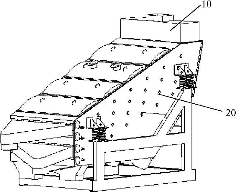
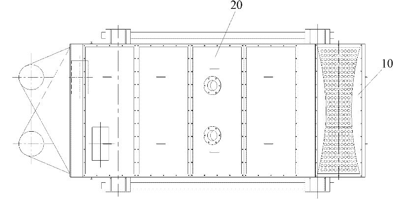
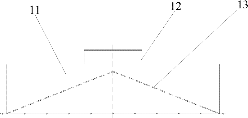
[0039] figure 1 and figure 2 A perspective view and a top view of a vibration screening device according to a preferred embodiment of the present invention are respectively shown. From figure 1 , figure 2 As can be seen in the figure, the vibrating screening device includes a feeding device 10 and a vibrating material distributing device 20, and the feeding device 10 is detachably installed above the vibrating material distributing device 20, specifically, installed on the top of the vibrating screening device 20 entrance (not shown). Below, refer to Figure 3a , 3b , 3c describe the overall structure of the above-mentioned feeding device 10 . This feeding device 10 comprises: feeding box body 11, and its top is provided with feeding port 12 (as Figure 9 shown); the distribution screen 13, which is arranged ...


PUM


Abstract

The invention provides a material separation screen plate, a vibration screen device comprising the material separation screen plate, as well as stirring equipment comprising the device, and generally relates to the field of engineering equipment. A plurality of feed holes are formed on the material separation screen plate, and the material separation screen plate is of a middle-high peripheral-low structure, and is provided with opposite inner concave lateral sides in which projections in vertical direction are of inner concave shapes. The vibration screen device comprises a feed device and a vibration separation device, and the feed device is detachably arranged at the inlet on the top of the vibration separation device, wherein the feed device comprises a feed case and a separation screen plate, wherein a feed port is formed on the top of the feed case; and the separation screen plate is arranged inside the feed case, and a plurality of inlet holes are formed on the separation screen plate. The vibration screen device has a simple structure, is convenient to assemble and disassemble, and realizes that the separation effect is improved, so that a material can be uniformly distributed on a screen after entering from the feed port.

Description

technical field [0001] The invention relates to the field of engineering equipment, in particular to a material distribution screen, a vibration screening device including the material distribution screen, and a stirring device including the device. Background technique [0002] In the vibrating screening device currently used in dry-mixed mortar mixing equipment, the feeding port of the vibrating screen adopts two feeding methods: [0003] 1. Direct feeding method. In this way, the vibrating screen is fed by a vibrating feeder, and no distributing device is used in this way; [0004] 2. Feeding by material distribution device. In this way, the distributing device is located inside the vibrating screen, and a baffle plate is welded at the lower end of the feed inlet, and an "eight"-shaped material guide rib is welded on it, which acts as a distributing device, and the "eight" The glyph-shaped material guide rib can disperse part of the material to both sides when it falls...

Claims


Application Information

Patent Timeline
Patent Type & Authority Applications(China)
IPC IPC(8): B07B1/46B07B1/28B01F15/02
CPCB07B13/16B07B1/46B07B1/28B01F15/02
Inventor 景斌
Owner ZOOMLION HEAVY IND CO LTD
Why Eureka
Try Eureka