
Inertia friction welding physical simulation test device

A friction welding and physical simulation technology, applied in welding equipment, non-electric welding equipment, metal processing equipment, etc., can solve the problems of not being able to respond to the temperature of the weld zone in real time, hindering the real-time monitoring of infrared thermometers, and being unable to observe the temperature field.

Inactive Publication Date: 2013-06-19
NORTHWESTERN POLYTECHNICAL UNIV
View PDF5 Cites 0 Cited by
  • Summary
  • Abstract
  • Description
  • Claims
  • Application Information

AI Technical Summary

Problems solved by technology

The former cannot reflect the temperature of the weld area in real time due to the lagging reaction of the thermocouple; the latter hinders the real-time monitoring of the surface temperature of the weld by the infrared thermometer due to the flash and spatter of the welding process, and cannot monitor the temperature field inside the weld. to observe the changes
According to the retrieval of relevant literature, there is no report involving the inertial friction welding physical simulation test device. Therefore, a physical simulation test device with simple process and convenient operation for studying the plastic metal flow behavior of the inertial friction welding joint and the distribution of the weld temperature field is sought. become an urgent problem to be solved in this field

Method used


Image

  • Inertia friction welding physical simulation test device
  • Inertia friction welding physical simulation test device
  • Inertia friction welding physical simulation test device

Examples


Embodiment Construction

[0014] Now in conjunction with embodiment, accompanying drawing, the present invention will be further described:

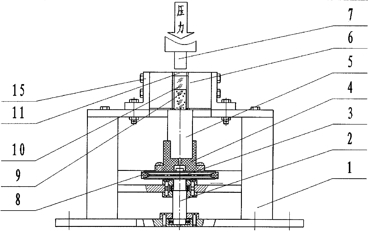
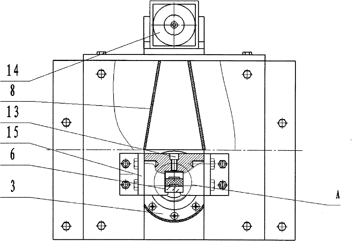
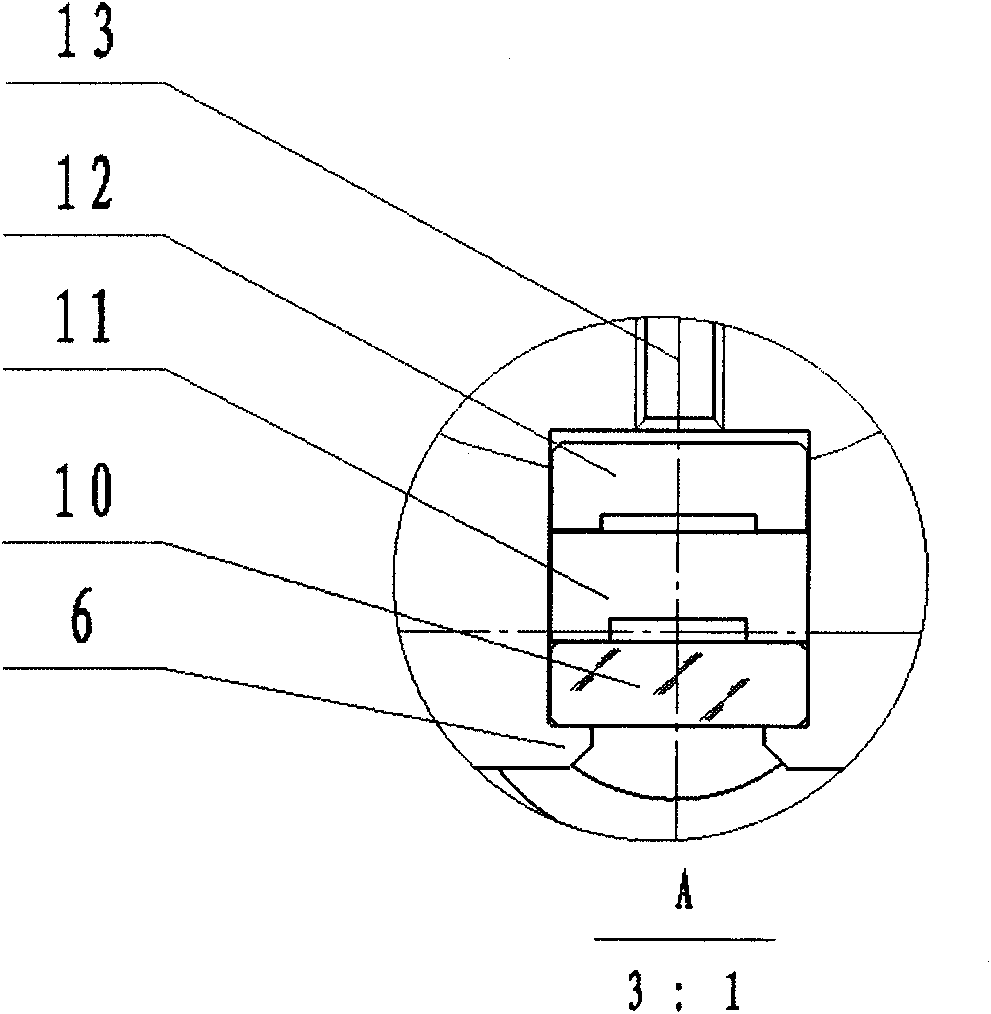
[0015] Refer to attached figure 1 , the inertial friction welding physical simulation experiment device includes a base 1, a shaft 2, a belt pulley 3, a bracket 4, a heating body 5, a fixed block 6, a pressure head 7, a belt 8, a test piece 9, an infrared transparent material 10, and a bakelite groove 11. Adjusting plate 12, adjusting nut 13, driving motor 14, L-shaped bracket 15. The shaft 2 is installed on the lower part of the base 1 through bearings, the belt pulley 3 is fixed on the top of the shaft 2 by pins, the bracket 4 is fixed on the belt pulley 3 by screws, the heating body 5 is installed on the bracket 4, and the heating body 5 The upper end is close to the lower end of the fixed block 6; one side of the fixed block 6 is provided with a T-shaped groove, and the fixed block 6 is fixed on the top of the base by an L-shaped bracket 15; the infrared mat...


PUM


Abstract

The invention relates to an inertia friction welding physical simulation test device, which is characterized in that a shaft is arranged on a pedestal of a base through a bearing, a belt pulley is fixed on an upper end of the shaft through a pin, the belt pulley is connected with a driving motor through a belt; a bracket is fixed on the belt pulley through a bolt, a heating body is arranged on the bracket; a fixed block is arranged on an upper end of the heating body, a T-shaped groove is arranged on one side of the fixed block; the fixed block is fixed on the top end of the base through an L-shaped bracket; an infrared transmitting material, a bakelite groove and an adjusting plate are arranged in the T-shaped groove of the fixed block; a pressure head capable of pressing downwards is arranged right above the bakelite groove; a size of the pressure head is matched with that of a test-piece cavity. The invention is capable of simulating metal plastic flow behaviour of an inertia friction welding head and monitoring welding line temperature field distribution, and has a simple structure and convenient operation.

Description

technical field [0001] The invention relates to a friction welding physical simulation test device, in particular to an inertia friction welding physical simulation device for simulating the plastic metal flow behavior of an inertia friction welding joint and monitoring the temperature field of the butt joint. Background technique [0002] Inertial friction welding technology is a solid phase connection technology invented by the American Tracked Vehicle Company in 1962. Inertial friction welding is a type of friction welding in which the energy required for welding is mainly provided by the rotational kinetic energy stored on the welding machine. In inertial welding, one of the workpieces is attached to a flywheel while the other does not rotate. Accelerate the flywheel to a predetermined speed to store the required energy, then disengage the drive motor and use the upsetting force to press the workpieces down and rub against each other. As the speed of the flywheel decre...

Claims


Application Information

Patent Timeline
Patent Type & Authority Patents(China)
IPC IPC(8): B23K20/12B23K20/26
Inventor 马铁军鲍宏伟高大路李文亚李京龙
Owner NORTHWESTERN POLYTECHNICAL UNIV
Learn More