Automatic control transfer printing device

A technology of transfer printing and blanket tape, applied in transfer printing, rotary printing machine, printing, etc., to achieve the effect of good output quality, convenient operation and stable operation

Active Publication Date: 2011-12-21
NEWTECH TEXTILE TECH DEV SHANGHAI
View PDF13 Cites 20 Cited by
  • Summary
  • Abstract
  • Description
  • Claims
  • Application Information

AI Technical Summary

Problems solved by technology

[0003] In order to overcome some problems existing in the transfer printing device of the existing transfer printing machine, and solve many problems and shortcomings of the roller tran...

Method used


Image

  • Automatic control transfer printing device
  • Automatic control transfer printing device
  • Automatic control transfer printing device

Examples


Embodiment 1

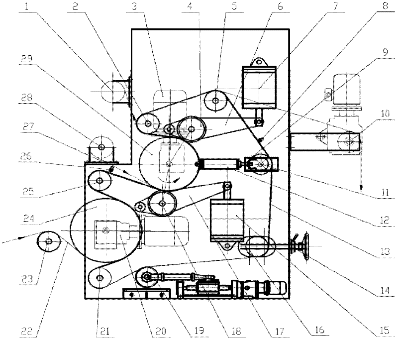
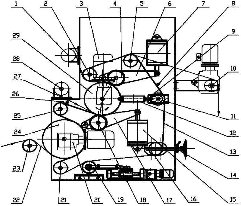
[0029] figure 1 A schematic structural view of Embodiment 1 of an automatic control type transfer printing device is shown.

[0030] The automatic control type transfer printing device of embodiment 1 includes left and right frames, main roller, heating roller, endless blanket belt, support guide roller, adjustment guide roller, tension guide roller, uniform pressure roller, correction guide roller and accessory parts. figure 1 Only one side of the rack is shown. On the left and right frames, a main roller 29 and a heating roller 24 are fixedly connected by bearings and bearing seats (not shown), and eight various guide rollers that play the role of supporting rollers are connected by bearings and bearing seats; The blanket belt 13 is wrapped around the eight supporting rollers and kept in contact with the main roller and the heating roller through the eight supporting rollers, and there is a deflection guide roller in contact with the outer peripheral surface of the endless ...

Embodiment 2

[0043] The automatic control transfer printing device in Embodiment 2 is basically the same as the automatic control transfer printing device in Embodiment 1, and this embodiment only describes the different parts.

[0044] The first uniform pressure roller 18 contacts the entrance contact pressure line of the main roller 29 via the blanket belt and is located at the counterclockwise direction of the entrance tangent of the main roller 29. The second uniform pressure roller 4 is connected to the main roller through the blanket belt. The contact pressure line at the exit of 29 contacts is at the place where the main roller 29 exit tangent rotates 40° in the clockwise direction, and the ring-shaped blanket belt occupies 5 / 18 of the main roller circumference between the two uniform pressure roller inlet and outlet contact pressure lines. noodle.

[0045] The pressure device of tension guide roller 11 and uniform pressure roller 4 and 18 adopts hydraulic pressure device, so that a...


PUM


Abstract

The invention relates to an automatic-control type transfer-printing device, wherein a first supporting guide roller and a second supporting guide roller are located at a combined inlet of a main roller and an annular carpet strip and a separated outlet of the main roller and the annular carpet strip; an inlet tangent line and an outlet tangent line where the first and the second supporting guide rollers are tangential to the main roller are located in the same plane where the central axis of the main roller is located; the inlet tangent line is parallel to the outlet tangent line; two ends of a tensioning guide roller are connected into a slideway of a frame and are connected with a lifting rod; two equalizing press rollers are connected to a connecting lever, one end of the connecting lever is connected with the frame, and the other end of the connecting lever is connected with the lifting rod, so that pressurizing lines where the first and the second equalizing press rollers are in contact with the main roller are located between the inlet tangent line and the outlet tangent line of the main shaft; one shaft end of an offsetting guide roller is connected to the frame, and the other shaft end of the offsetting guide roller is connected into the slideway of the frame and is connected with a carpet strip tension-regulating mechanism; the annular carpet strip is in contact with 1/2 of a circumferential face of the main roller and is in contact with 1/3-2/3 of a circumferential face of a heating roller; and one shaft end of a rectifying guide roller is connected with the frame at one side and the other shaft end of the rectifying guide roller is connected with a rectifying mechanism at the other side of the frame. The transfer-printing device is convenient to operate and stable to run.

Description

technical field [0001] The invention relates to a printing and dyeing machine in the textile industry, in particular to an automatic control transfer printing device suitable for natural fiber fabrics. This automatic control type transfer printing device is aimed at many problems existing in the existing transfer printing device, and has carried out transformation and innovation on the machinery and automatic controller to make the production of transfer printing more stable. Background technique [0002] Transfer printing is a new process and new technology in the field of textile printing and dyeing. Compared with traditional printing, transfer printing has many advantages, especially in terms of water saving and less water in printing production. Transfer printing is an environmentally friendly production process and technology, which conforms to the current green ecological concept of emission reduction and low carbon, and is a new technology for promotion and applicatio...

Claims


Application Information

Patent Timeline
IPC IPC(8): B41F16/02
Inventor 钟博文
Owner NEWTECH TEXTILE TECH DEV SHANGHAI
Why Eureka
Try Eureka