Hydraulic jetting drilling-well shower nozzle
A technology of hydraulic jetting and nozzles, which is applied in the direction of drilling with liquid/gas jetting, which can solve the problems of small hole diameter and inability to form nozzles, and achieve the effects of fast rock breaking speed, prevention of undercutting, and high wear resistance
- Summary
- Abstract
- Description
- Claims
- Application Information
AI Technical Summary
Problems solved by technology
Method used
Image
Examples
specific Embodiment approach
[0025] Five, specific embodiment: the present invention will be further described below in conjunction with accompanying drawing:
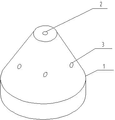
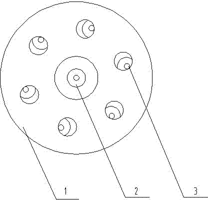
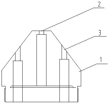
[0026] figure 1 is an overall schematic diagram of the present invention, figure 2 It is a bottom view of the present invention, image 3 is a longitudinal sectional view of the present invention, Figure 4 It is the side development view of the side hole of the present invention, combined with figure 1 , figure 2 , image 3 , Figure 4 As shown, the hydraulic jet drilling nozzle includes a nozzle body 1. There is a water outlet hole on the nozzle body 1, and there are longitudinally arranged water outlet channels connected to the water outlet holes. The nozzles are built in the water outlet channels, and the nozzles play the role of pressurizing the water column. The nozzle body 1 is conical with a flat end at the front end. The flat end is to provide a certain wall thickness for the nozzle in the nozzle body 1, so as to prevent the refle...
Embodiment 1
[0036] The hydraulic jet drilling sprinkler head includes a nozzle body 1. There is a water outlet hole on the nozzle body 1, and there are longitudinally arranged water outlet channels inside to communicate with the water outlet holes. Nozzles are built in the water outlet channels. The nozzle body 1 is conical with a flat end at the front end. The water outlet hole includes a middle hole 2 and six side holes 3, the middle hole 2 is located on the flat end of the front end of the nozzle body 1, the six side holes 3 are located on the conical slope of the nozzle body 1, and the side holes 3 are centered on the middle hole 2. The centers are arranged radially. The water outlet channel of the middle hole 2 is in the same direction as the nozzle axis, and the water outlet channel of the side hole 3 is inclined 5° along the tangential direction, forming a clockwise inclination angle, and the inclination direction of the water outlet channel of the side hole 3 is consistent. The w...
Embodiment 2
[0038] The hydraulic jet drilling sprinkler head includes a nozzle body 1. There is a water outlet hole on the nozzle body 1, and there are longitudinally arranged water outlet channels inside to communicate with the water outlet holes. Nozzles are built in the water outlet channels. The nozzle body 1 is conical with a flat end at the front end. The water outlet hole includes a middle hole 2 and six side holes 3, the middle hole 2 is located on the flat end of the front end of the nozzle body 1, the six side holes 3 are located on the conical slope of the nozzle body 1, and the side holes 3 are centered on the middle hole 2. The centers are arranged radially. The water outlet channel of the middle hole 2 is in the same direction as the nozzle axis, and the water outlet channel of the side hole 3 is inclined 8° along the tangential direction, forming a clockwise inclination angle, and the inclination direction of the water outlet channel of the side hole 3 is the same. The...
PUM
 Abstract
Description
Claims
Application Information
 - R&D
- Intellectual Property
- Life Sciences
- Materials
- Tech Scout
- Unparalleled Data Quality
- Higher Quality Content
- 60% Fewer Hallucinations
Browse by: Latest US Patents, China's latest patents, Technical Efficacy Thesaurus, Application Domain, Technology Topic, Popular Technical Reports.
© 2025 PatSnap. All rights reserved.Legal|Privacy policy|Modern Slavery Act Transparency Statement|Sitemap|About US| Contact US: help@patsnap.com


