
A solenoid valve control circuit

A technology of control circuit and main control circuit, applied in valve details, valve device, valve operation/release device, etc., can solve the problems affecting test accuracy and test efficiency, unstable airflow, large resistance, etc., to achieve reliable performance, The effect of fast response and low cost

Inactive Publication Date: 2011-12-21
江苏茶花电气股份有限公司
View PDF5 Cites 10 Cited by
  • Summary
  • Abstract
  • Description
  • Claims
  • Application Information

AI Technical Summary

Problems solved by technology

In the process of adjustment, the speed is slow, due to the large resistance, and the air flow from the valve is unstable, which affects the test accuracy and test efficiency

Method used


Image

  • A solenoid valve control circuit
  • A solenoid valve control circuit

Examples


Embodiment Construction

[0022] In order to make the technical means, creative features, goals and effects achieved by the present invention easy to understand, the present invention will be further described below in conjunction with specific embodiments.

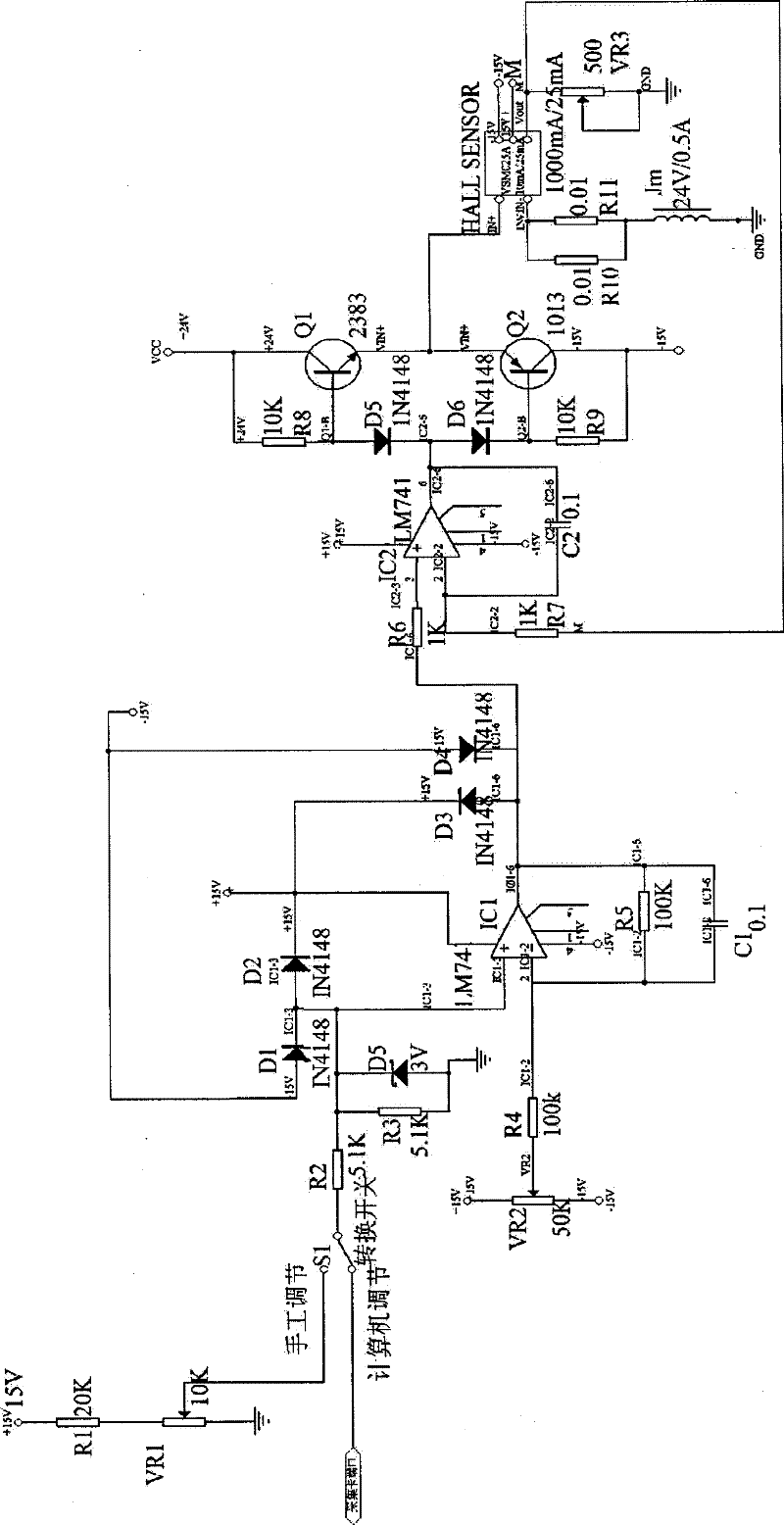
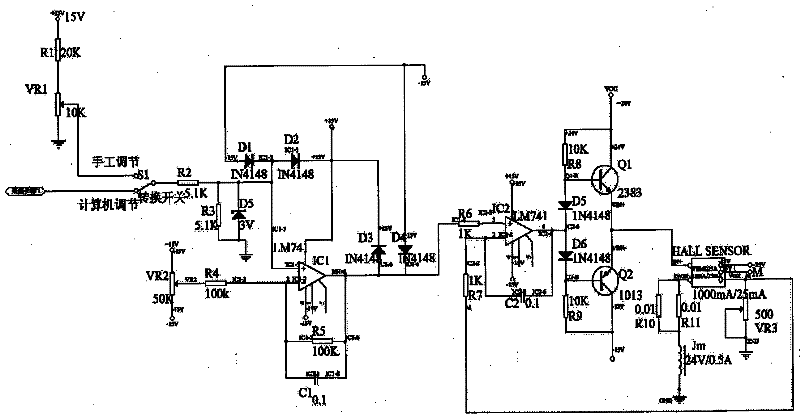
[0023] Such as figure 1 As shown, a solenoid valve control circuit includes a solenoid valve Jm, a regulating device and a main control circuit, the main control circuit and the regulating device are connected through a transfer switch S1, the regulating device controls the solenoid valve Jm through the main control circuit, and the regulating device is manually adjusted device or computer adjustment device, the manual adjustment device is the first potentiometer VR1, the first potentiometer VR1 is connected to the first resistor R1 and then connected to the transfer switch S1, and the computer adjustment device is connected to the computer acquisition port through the transfer switch S1. The main control circuit includes an outer closed-loop cont...


PUM


Abstract

The invention discloses an electromagnetic valve control circuit which comprises an electromagnetic valve, regulating devices and a main control circuit; the main control circuit and the regulating devices are connected through a change-over switch; the regulating devices control the electromagnetic valve through the main control circuit; and the main control circuit comprises an external closed loop control system circuit and an internal reference circuit. The electromagnetic valve control circuit has the beneficial effects that: a plurality of regulating devices are connected with the main control circuit, so that the different levels of operation of an operator are convenient, and the circuit has a simple design, low cost and reliable performance. The design of the reference circuit ismore convenient to calibrate and operate by the operator. Due to the design of the external closed loop control circuit, the control circuit has strong anti-interference capability, good stability and high reaction speed.

Description

technical field [0001] The invention relates to a control circuit, in particular to a Hall feedback control circuit for an electromagnetic valve. Background technique [0002] There are many kinds of solenoid valves on the market, and the control method is nothing more than manually adjusting the control voltage of the solenoid valve and adding a controllable constant current voltage. By manually controlling the working voltage of the solenoid valve, the rotation angle of the solenoid valve can be controlled, and then the air flow can be controlled. Manual control has poor precision, low efficiency, and is difficult to locate accurately. At the same time, the interference of the power supply is large, the airflow fluctuates greatly, and the maintenance cost is high. The mechanical handle is used to adjust the pressure division, and the control method is susceptible to interference and the adjustment handle is vulnerable. In the process of adjustment, the speed is slow, due ...

Claims


Application Information

Patent Timeline
Patent Type & Authority Applications(China)
IPC IPC(8): F16K31/06
Inventor 王卫国覃孝梅杨冶
Owner 江苏茶花电气股份有限公司
Learn More