
A method and device for measuring bolt torque coefficient

A technology of torque coefficient and detection device, applied in the field of thread tightening, can solve the problems of excessive elastic deformation of connecting rods, different friction coefficients, and different torque coefficients are not considered, so as to ensure reliability, improve accuracy, and greatly adapt to sexual effect

Inactive Publication Date: 2011-12-21
SANY ELECTRIC CO LTD
View PDF4 Cites 16 Cited by
  • Summary
  • Abstract
  • Description
  • Claims
  • Application Information

AI Technical Summary

Problems solved by technology

However, there will always be some differences between the scene of the laboratory testing and the actual assembly site
For example, due to the different surface quality of the connected parts, the friction coefficient between the fastener and the connected rod will also be different; especially, when the bolt is connected to the threaded hole, the threaded hole formed on-site will be mechanically processed and connected. Depending on the material of the threaded fastener, the surface friction coefficient of the threaded hole will always be different; such a difference will lead to an excessively large difference between the actual tightening torque applied to the threaded fastener and the theoretical tightening torque, and the elastic deformation of the connecting rod may be too large. Large, or too small, making it difficult to ensure the reliability of threaded fastener connections
[0005] In addition, although the corresponding technical standards also give the tightening torque that should be applied to different threaded fasteners, the tightening torque does not take into account the different torque coefficients caused by different assembly site conditions, and it is difficult to meet the requirements of different assembly sites. Requirements for connection reliability of threaded fasteners

Method used


Image

  • A method and device for measuring bolt torque coefficient
  • A method and device for measuring bolt torque coefficient
  • A method and device for measuring bolt torque coefficient

Examples


Embodiment Construction

[0034] The present invention will be described in detail below in conjunction with the accompanying drawings. The description in this part is only exemplary and explanatory, and should not be regarded as limiting the technical content disclosed in the present invention.

[0035] For ease of understanding, this part first describes the device for measuring the bolt torque coefficient, and then describes the method for measuring the bolt torque coefficient provided by the invention.

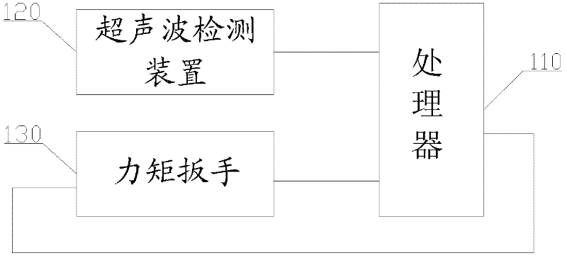
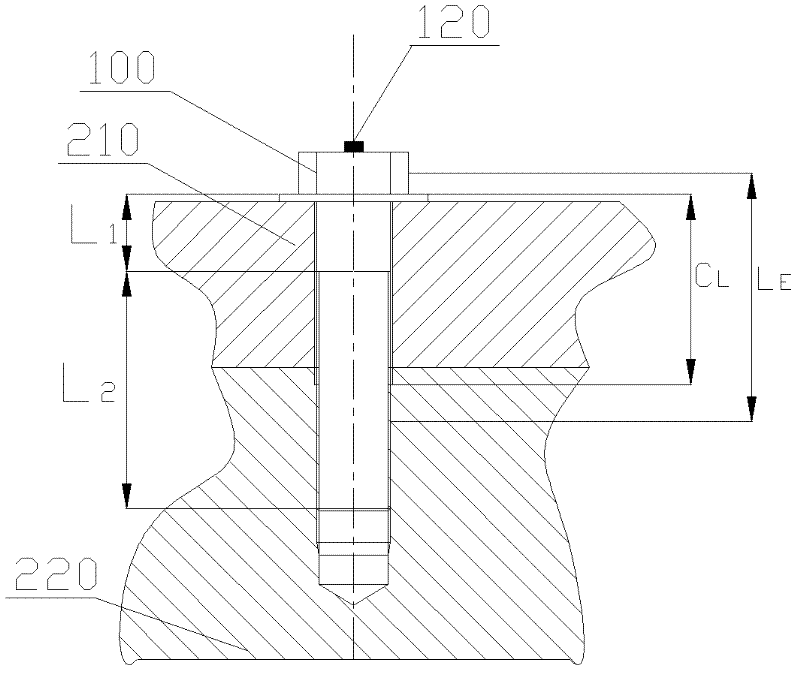
[0036] Please refer to figure 1 and figure 2 , figure 1 It is a structural block diagram of a device for measuring bolt torque coefficient provided by the present invention; figure 2 It is a schematic diagram of the working principle of the device for measuring the bolt torque coefficient provided by the present invention.

[0037] The device for measuring the bolt torque coefficient provided by the present invention includes a processor 110, an ultrasonic detection device 120 and a torque wre...


PUM


Abstract

The invention discloses a method and a device for determining a torque coefficient of a bolt. By the method, a preset torque T which is applied to a screw fastener and the extension amount of the screw fastener are obtained; an axial load of the screw fastener is obtained according to the extension amount; and the torque coefficient of the screw fastener is obtained according to the preset torqueand the axial load. By the method, an error of the torque coefficient caused by difference between a detection scene and an actual installation scene can be avoided, the accuracy of the determined torque coefficient of the screw fastener is improved; meanwhile, when the screw fastener is in fit with a threaded hole which is formed in a connected piece, the torque coefficient of the screw fastenercan be determined by using the method. Therefore, the method is higher in adaptability. According to the torque coefficient, a tightening torque of the corresponding screw fastener can be corrected, so the difference between an applied actual tightening torque and a theoretical tightening torque is smaller, and the connection reliability of the screw fastener is guaranteed.

Description

technical field [0001] The invention relates to a thread fastening technology, in particular to a method and device for measuring bolt torque coefficient. Background technique [0002] Threaded fastener connection is a commonly used connection method at present. Generally speaking, in wind turbines, the connection of large parts is mainly connected by threaded fasteners. The threaded fastener connection includes the corresponding connecting rod, the connecting rod passes through the connected parts, and the corresponding parts are set at both ends of the connecting rod to fix the two or three connected parts together; there are mainly four kinds of fits for threaded fasteners Relationship: The first is that the two ends of the stud are matched with the nut and the threaded hole respectively, and the stud forms a connecting rod; the second is that the bolt and the nut are matched, and the rod-shaped part of the bolt forms a connecting rod; the third is that the bolt and the ...

Claims


Application Information

Patent Timeline
IPC IPC(8): G01L5/24
Inventor 谢铭辉魏振山任延博
Owner SANY ELECTRIC CO LTD
Learn More