Installation method for forging machine motor rotor and photoelectric sensor

A photoelectric sensor and motor rotor technology, applied in electromechanical devices, manufacturing motor generators, electrical components, etc., can solve problems such as eccentricity and control failure of circular grating sensors

Active Publication Date: 2013-05-22
中船西安东仪科工集团有限公司
View PDF3 Cites 0 Cited by
  • Summary
  • Abstract
  • Description
  • Claims
  • Application Information

AI Technical Summary

Problems solved by technology

[0003] The purpose of the present invention is to provide a method for installing the motor rotor and photoelectric sensor of a forging machine tool to solve the problem of eccentricity of the circular grating sensor in the current forging machine tool, resulting in control failure

Method used


Image

  • Installation method for forging machine motor rotor and photoelectric sensor
  • Installation method for forging machine motor rotor and photoelectric sensor

Examples


Embodiment Construction

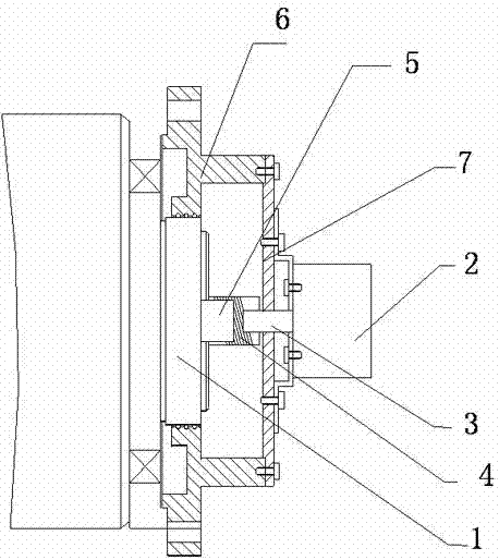
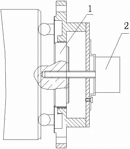
[0013] Such as figure 1 and figure 2 As shown, a method for installing a motor rotor and a photoelectric sensor of a forging machine tool includes a motor and a circular grating sensor 2 arranged on the motor rotor for transmitting control signals, and the outer end of the rotor main shaft 1 is circumferentially arranged There are bearings and a bearing cover 6, and the bearing cover 6 has a screw hole that is fixed with the sensor bridge 7, and the circular grating sensor 2 is fixed at the center opening of the sensor bridge, and the circular grating sensor 2 passes through the sensor bridge 7 and the bearing cover. 6 is fixed, the rotor pin shaft 5 protrudes concentrically from the rotor main shaft 1, and the circular grating sensor 2 extends inwards from the sensor shaft 3, and the interfering connector 4 transitions between the rotor pin shaft 5 and the sensor shaft 3 , so that the circular grating sensor 2 is electrically connected with the motor rotor.

[0014] In ord...


PUM


Abstract

The invention relates to a forging machine, in particular relates to the velocity measurement of a motor rotor in the forging machine and particularly provides an installation method for a forging machine motor rotor and a photoelectric sensor. In the process provided by the invention, a motor and a radial grating sensor which is arranged on the motor and is used for transferring a control signalare utilized, wherein a bearing outer cover is arranged on the circumferential direction of the outer end part of the main shaft of the rotor, a screw hole is arranged on the bearing outer cover and is fixed together with a sensor bridge in a matching manner, the radial grating sensor is fixed at the central mouth of the sensor bridge and is fixed together with the bearing outer cover through thesensor bridge, a rotor hinge pin extends outwards with the same axle center of the main shaft of the rotor, the radial grating sensor extends inwards to be provided with sensor small shaft, and an interference connector is arranged between the rotor hinge pin and the sensor small shaft for transition, so that the radial grating sensor can be electrically connected with the motor rotor. According to the invention, the problem of control failure caused by the eccentric radial grating sensor existing in the existing forging machines is solved.

Description

technical field [0001] The invention relates to a forging machine tool, in particular to a rotor speed measurement control of a motor in the forging machine tool, specifically a method for installing the motor rotor and a photoelectric sensor of the forging machine tool. Background technique [0002] The sensor used by the forging machine tool is a circular grating sensor with an aperture of φ8mm, and the diameter of the rotor shaft of the motor is φ160mm, such as figure 1 As shown, the current installation method is to process an M8 threaded hole on the rotor shaft, and connect the circular grating sensor to the rotor shaft with M8 screws. The screw connection cannot guarantee concentricity, and it is easy to loosen during the vibration process. , the circular grating sensor is off-center, and the information fails, which leads to the control failure. Contents of the invention [0003] The purpose of the present invention is to provide a method for installing the motor r...

Claims


Application Information

Patent Timeline
Patent Type & Authority Patents(China)
IPC IPC(8): H02K15/00H02K11/00H02K11/22
Inventor 张爱华王毅刘旭孙斌
Owner 中船西安东仪科工集团有限公司
Why Eureka
Try Eureka