The installation structure of the connection terminal of the photovoltaic junction box

A technology for connecting terminals and volt junction boxes, applied in the field of photovoltaic power generation, which can solve problems affecting device performance, insufficient heat resistance, and rising production costs, and achieve the effects of improving reliability, reducing temperature, and facilitating cost control

Active Publication Date: 2011-12-21
浙江正泰鑫辉光伏有限公司
View PDF5 Cites 14 Cited by
  • Summary
  • Abstract
  • Description
  • Claims
  • Application Information

AI Technical Summary

Problems solved by technology

This design scheme has the following two disadvantages: one is that the connection terminals are directly installed in the base of the photovoltaic junction box, and the heat generated on the connection terminals will be directly conducted to the base of the photovoltaic junction box, so the base of the photovoltaic junction box is required Has high heat resistance
However, the base of the existing photovoltaic junction box is generally to save costs, and the heat resistance of the material used is often not high enough, which in turn affects the performance of the entire device; if the heat resistance of the base is to be enhanced, the production cost will increase.
Second, heat-conducting insulators need to be filled between the heat-dissipating support and the diode, which also leads to an increase in cost

Method used


Image

  • The installation structure of the connection terminal of the photovoltaic junction box
  • The installation structure of the connection terminal of the photovoltaic junction box
  • The installation structure of the connection terminal of the photovoltaic junction box

Examples


Embodiment Construction

[0024] The specific embodiments of the present invention will be further described below in conjunction with the accompanying drawings.

[0025] The present invention is composed of the following parts: connecting terminal assembly, diode, mounting plate, photovoltaic junction box base.

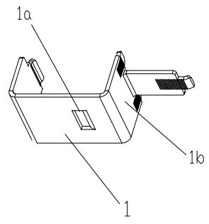
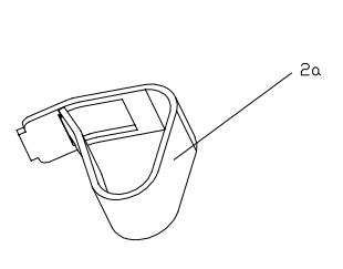
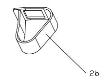
[0026] First, the connection terminal assembly is introduced, which includes a terminal body 1 , a wire clip 2 a , a bus strip clip 2 c , two diode clips 2 b and a heat dissipation support 3 . Such as figure 1 As shown, the terminal main body 1 is composed of several end surfaces connected vertically to each other. Such as figure 2 , image 3 , Figure 4 As shown, the wire clip 2a, the diode clip 2b and the bus clip 2c all adopt a cage structure. Image 6 The structure of the heat dissipation support is shown.

[0027] The assembly relationship of the terminal body 1, the wire clamp 2a, the bus strip clamp 2c and the diode clamp 2b is as follows: Figure 5 As shown, the terminal body ...


PUM


Abstract

The invention discloses a mounting structure of a photovoltaic junction box connecting terminal. The mounting structure comprises a photovoltaic junction box base, a connecting terminal assembly and a diode; a mounting board is arranged in the photovoltaic junction box base; the connecting terminal assembly and the diode are installed on the mounting board; and the mounting board is connected in the photovoltaic junction box base in a clamping manner or is integrally injection molded in the photovoltaic junction box base. As the connecting terminal assembly is connected with the photovoltaic junction box base through the mounting board, the mounting board can adopt heat resistance and high intensity materials and can meet the requirement on the performance, moreover, as the mounting board is small in volume, the cost can be controlled, and the removable design of the mounting board is also convenient for automatic assembling and maintenance. In addition, the diode is arranged between two connecting terminals, a diode shell clings to one end of a radiating support element, so that the heat of the diode can be fast transferred to the radiating support element, the temperature of the diode can be reduced and the reliability of the diode can be improved.

Description

technical field [0001] The invention relates to the field of photovoltaic power generation, in particular to an installation structure applied to a connection terminal of a photovoltaic junction box in a photovoltaic power generation system. Background technique [0002] The Chinese patent application specification with application number 201120148410.2 discloses a photovoltaic junction box connection terminal group and its components with heat dissipation function. This design scheme has the following two disadvantages: one is that the connection terminals are directly installed in the base of the photovoltaic junction box, and the heat generated on the connection terminals will be directly conducted to the base of the photovoltaic junction box, so the base of the photovoltaic junction box is required Has high heat resistance. However, the base of the existing photovoltaic junction box is generally used to save costs, and the heat resistance of the material used is often n...

Claims


Application Information

Patent Timeline
Patent Type & Authority Applications(China)
IPC IPC(8): H02N6/00H02G3/08H02S40/34
CPCY02E10/50
Inventor 彭祁军朱清涛
Owner 浙江正泰鑫辉光伏有限公司
Why Eureka
Try Eureka