A steel cage lifting structure

A lifting structure and reinforcement cage technology, applied in the field of reinforcement cages, can solve problems such as safety accidents, separation of reinforcing hoop and main reinforcement, and no clear requirements, and achieve the effect of ensuring lifting safety.

Inactive Publication Date: 2011-12-28
ZHONGTIAN CONSTR GROUP +1
View PDF7 Cites 8 Cited by
  • Summary
  • Abstract
  • Description
  • Claims
  • Application Information

AI Technical Summary

Problems solved by technology

There is no clear requirement on the position of the reinforcement hoop in the specification. Generally speaking, the reinforcement hoop 1 is welded on the outside of the main reinforcement ring 2 composed of the main reinforcement. However, during the hoisting process of the reinforcement cage, once the lifting point is stressed, the steel wire rope 3 is tightened. The main reinforcement will be subjected to the inward side pressure of the steel wire rope, especially at the end of the hoisting, the reinforcement cage is close to vertical, and only the lifting point C is the stress point. At this time, if the reinforcement hoop and the main reinforcement are not welded firmly, it is easy to cause the reinforcement hoop to separate from the main reinforcement , a safety accident occurred

Method used


Image

  • A steel cage lifting structure
  • A steel cage lifting structure
  • A steel cage lifting structure

Examples


Embodiment Construction

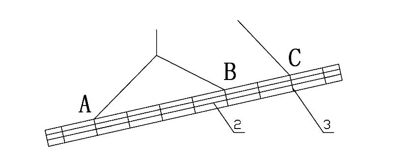
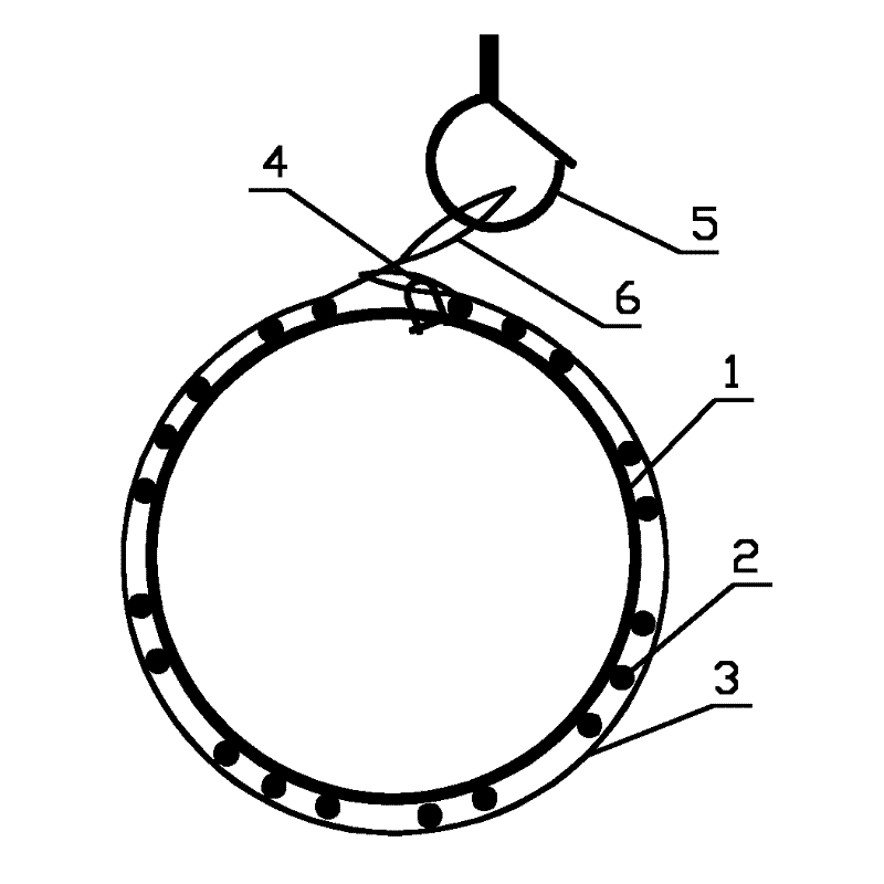
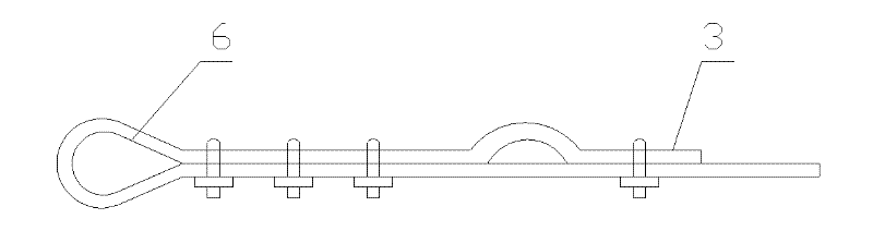
[0011] Such as Figure 1 to Figure 3 As shown, it is an embodiment of a steel cage lifting structure of the present invention. Several rings of reinforcing hoops 1 are welded to the inner ring of the main reinforcement ring 2 of the steel cage, and three steel wire ropes 3 are respectively sleeved on outside of the reinforcement cage and tighten the reinforcement cage. Both ends of the steel wire rope are provided with collars 6, one of which passes through the other end collar and hangs on the hook 5, and the other end collar is locked together with the reinforcing hoop through the shackle 4.


PUM


Abstract

The invention discloses a reinforcement cage lifting structure, which is welded to the inner ring of the main reinforcement ring of the reinforcement cage, and three steel wire ropes are respectively sleeved on the outside of the reinforcement cage at the lifting point A, the lifting point B and the lifting point C to tighten the reinforcement cage. Both ends of the steel wire rope are provided with collars, one of which passes through the other end collar and hangs on the hook, and the other end collar is locked together with the reinforcing hoop through a shackle. The present invention will be welded on the inner ring of the main reinforcement ring of the reinforcement cage. In this way, when lifting, the steel wire rope is tightened, and its inward side pressure is borne by the reinforcement hoop, and the main reinforcement is not stressed, so that the welding quality of the reinforcement hoop and the main reinforcement can be avoided. Accidents where the main reinforcement is detached from the reinforcement hoop due to poor performance.

Description

technical field [0001] The invention relates to building construction technology, in particular to a reinforcement cage. Background technique [0002] When the steel cage is hoisted for casing occlusal piles, if two steel cages are hoisted together, as figure 1 As shown, three lifting points are generally used for lifting. The three lifting points A, B, and C are respectively located in the left middle and right side of the steel cage. At this time, the length of the steel cage is more than 18 meters and the weight is more than 3 tons. When the reinforcement cage is close to vertical, the main point of force is the lifting point C, and the lifting points A and B are basically unstressed. Therefore, the welding quality of the reinforcing rib at the lifting point C is directly related to the safety of the reinforcement cage hoisting. There is no clear requirement on the position of the reinforcement hoop in the specification. Generally speaking, the reinforcement hoop 1 is we...

Claims


Application Information

Patent Timeline
Patent Type & Authority Applications(China)
IPC IPC(8): B66C1/12
Inventor 楼永良卢国豪蒋金生姚晓东纪学灵皮朝阳马科陆建飞
Owner ZHONGTIAN CONSTR GROUP
Why Eureka
Try Eureka