
Parallel-laid steel wire rope for container equipment and manufacturing method thereof

A wire rope and parallel laying technology, which is applied in the field of hoisting and traction wire rope manufacturing, can solve the problems of poor fatigue and mechanical properties of steel wires, easy wear of steel wires, broken wires and broken strands, shortened service life of steel wire ropes, etc. Great, long life effect

Inactive Publication Date: 2011-12-28
甘肃新实创科技有限公司
View PDF7 Cites 9 Cited by
  • Summary
  • Abstract
  • Description
  • Claims
  • Application Information

AI Technical Summary

Problems solved by technology

The structure of 25Fi is stable, but under the same diameter, the diameter of the steel wire used in the strand is relatively large, the fatigue and mechanical properties of the steel wire are poor, and it is not suitable for container equipment; the second layer of the 31WS structure and 36WS structure strands adopts two different diameters Steel wires, the two kinds of steel wires are arranged alternately, and the thin steel wires lie on the peak of the first layer of steel wires, which is very unstable. The thin steel wires of the outer layer move from the original position to the gap between the steel wires, which not only makes the outer layer of steel wires violate each other. The extrusion causes the structure to be unstable, and the steel wires of the outer strands of the steel wire rope are easy to wear, broken wires and broken strands, shortening the service life of the steel wire rope

Method used


Image

  • Parallel-laid steel wire rope for container equipment and manufacturing method thereof
  • Parallel-laid steel wire rope for container equipment and manufacturing method thereof
  • Parallel-laid steel wire rope for container equipment and manufacturing method thereof

Examples


Embodiment 1

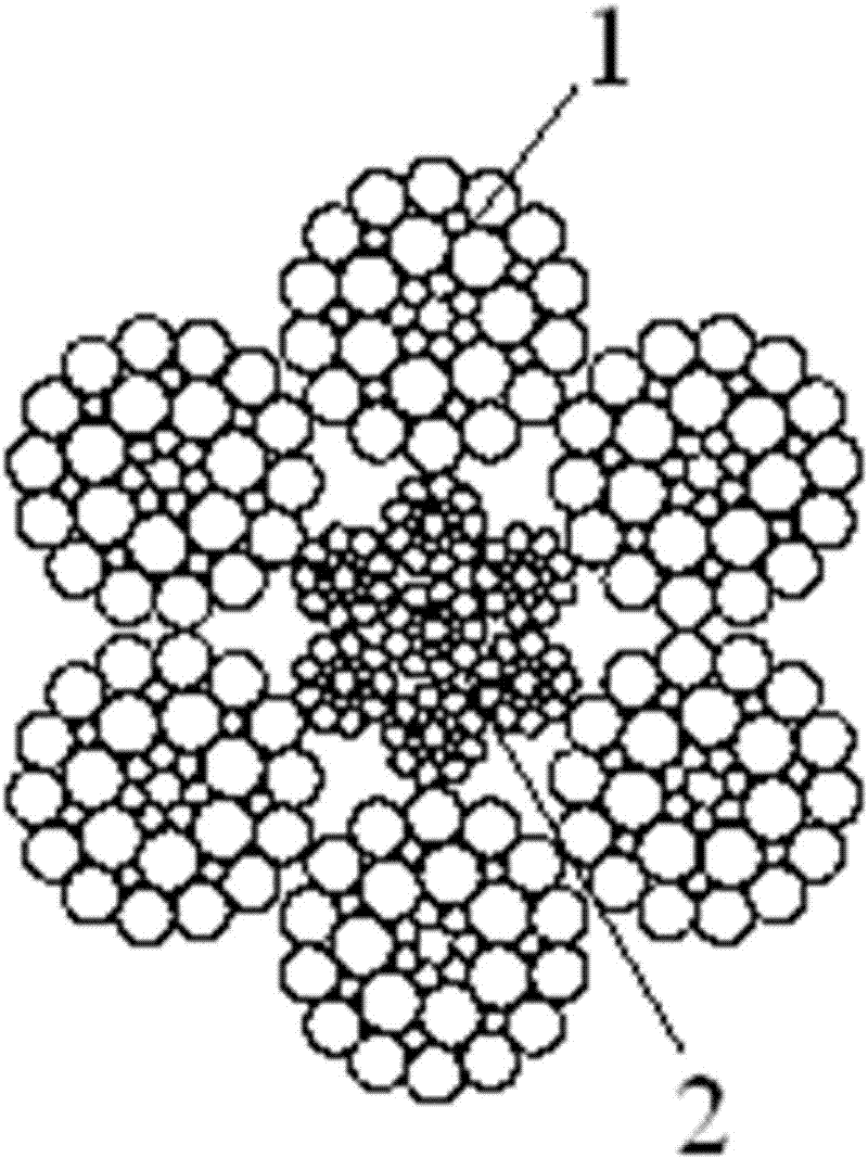
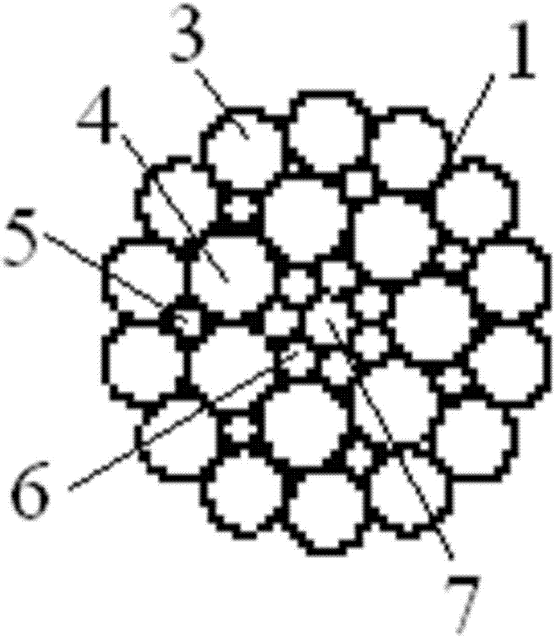
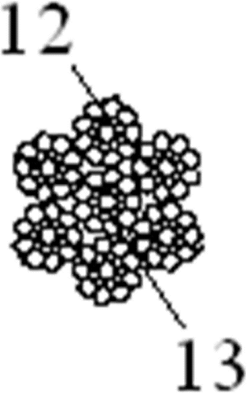
[0076] Determine that the diameter of the first outer layer steel wire 3 in the parallel twisted steel wire rope is 1.14mm, the diameter of the filling steel wire 5 is 0.82mm, the diameter of the first middle layer steel wire 4 is 1.80mm, the diameter of the first inner layer steel wire 6 is 0.72mm, and the diameter of the first center steel wire 7 The diameter is 1.57mm; the diameter of the second outer layer steel wire 9 is 0.95mm, the diameter of the second inner layer steel wire 10 is 0.46mm, the diameter of the second center steel wire 8 is 0.82mm; the diameter of the third outer layer steel wire 15 is 1.15mm, the third The inner steel wire 16 has a diameter of 0.56mm, and the third central steel wire 14 has a diameter of 1.00mm; according to the formula d n =d- 0 × (σ n / Kσ 0 ) 2 Calculate the diameter d of the raw steel wire corresponding to the above-mentioned finished steel wire with different diameters n : σ 0 Indicates the strength of 65# steel wire after quenc...

Embodiment 2

[0085]Determine that the diameter of the first outer layer steel wire 3 in the parallel twisted steel wire rope is 1.14mm, the diameter of the filling steel wire 5 is 0.82mm, the diameter of the first middle layer steel wire 4 is 1.80mm, the diameter of the first inner layer steel wire 6 is 0.72mm, and the diameter of the first center steel wire 7 The diameter is 1.57mm; the diameter of the second outer layer steel wire 9 is 0.95mm, the diameter of the second inner layer steel wire 10 is 0.46mm, the diameter of the second center steel wire 8 is 0.82mm; the diameter of the third outer layer steel wire 15 is 1.15mm, the third The inner steel wire 16 has a diameter of 0.56mm, and the third central steel wire 14 has a diameter of 1.00mm; according to the formula d n =d- 0 × (σ n / Kσ 0 ) 2 Calculate the diameter d of the raw steel wire corresponding to the above-mentioned finished steel wire with different diameters n : σ 0 Indicates the strength of 65# steel wire after quench...

Embodiment 3

[0090] Determine that the diameter of the first outer layer steel wire 3 in the parallel twisted steel wire rope is 1.14mm, the diameter of the filling steel wire 5 is 0.82mm, the diameter of the first middle layer steel wire 4 is 1.80mm, the diameter of the first inner layer steel wire 6 is 0.72mm, and the diameter of the first center steel wire 7 The diameter is 1.57mm; the diameter of the second outer layer steel wire 9 is 0.95mm, the diameter of the second inner layer steel wire 10 is 0.46mm, the diameter of the second center steel wire 8 is 0.82mm; the diameter of the third outer layer steel wire 15 is 1.15mm, the third The inner steel wire 16 has a diameter of 0.56mm, and the third central steel wire 14 has a diameter of 1.00mm; according to the formula d n =d- 0 × (σ n / Kσ 0 ) 2 Calculate the diameter d of the raw steel wire corresponding to the above-mentioned finished steel wire with different diameters n : σ 0 Indicates the strength of 65# steel wire after quenc...


PUM


Abstract

The invention discloses a parallel twisted steel wire rope used for a container device and a manufacture method thereof. The steel wire rope comprises a rope core, wherein six strands of first outer-layer strands are arranged around the rope core, and the multiple of the lay length of the steel wire rope is 6.0-6.5 times. According to the structure and the diameter of the steel wire rope, steel wire breaking force summation and requirements on the value of gaps mutually between the twisted steel wires, the diameter of a finished product steel wire used in the steel wire rope is calculated according to the triangular geometry relationship formula; the spiral angle and the twisted circle of each layer of steel wires are calculated by the lay length; the proportional relation among different layers of steel wires can be deducted; the diameter of the raw material steel wire is calculated; a 65# wire rod of which the diameter is 6.5mm is processed and is drawn into the raw material steel wire; the raw material steel wire is drawn into the finished product steel wire after being subjected to heat treatment; and the finished product steel wire is twisted into the parallel twisted steel wire rope. The position of each steel wire in the steel wire rope is on the peak base of an adjacent steel wire on a lower layer, the position is very stable, the phenomena of abrading, breaking wires and breaking strands have small possibility of happening, and the service life is prolonged.

Description

technical field [0001] The invention belongs to the technical field of hoisting and traction steel wire rope manufacturing, and relates to a steel wire rope suitable for hoisting equipment such as ports and quay bridges, in particular to a parallel-laid steel wire rope used for container equipment; How to make twisted steel wire rope. Background technique [0002] At present, the parallel-laid steel wire ropes used in container equipment such as ports and quay cranes generally adopt 25Fi structure, 31WS structure and 36WS structure. The structure of 25Fi is stable, but under the same diameter, the diameter of the steel wire used in the strand is relatively large, the fatigue and mechanical properties of the steel wire are poor, and it is not suitable for container equipment; the second layer of the 31WS structure and 36WS structure strands adopts two different diameters Steel wires, the two kinds of steel wires are arranged alternately, and the thin steel wires lie on the p...

Claims


Application Information

Patent Timeline
Patent Type & Authority Applications(China)
IPC IPC(8): D07B1/10
Inventor 曹玉德朱邦坤施荣标
Owner 甘肃新实创科技有限公司
Learn More