Eureka AIR delivers breakthrough ideas for toughest innovation challenges, trusted by R&D personnel around the world.

Floor type indoor ceiling concrete slab bottom drilling mechanism

A technology of concrete slab and drilling mechanism, which is applied in the direction of earthwork drilling, drilling equipment, supporting device, etc., can solve the problem that the equipment does not have technical significance, and achieve the effect of ensuring stability

Inactive Publication Date: 2011-12-28
常熟市金龙装饰有限责任公司
View PDF8 Cites 22 Cited by
  • Summary
  • Abstract
  • Description
  • Claims
  • Application Information

AI Technical Summary

Problems solved by technology

Since these technical solutions are all aimed at the installation of specific components, there is no technical significance for the equipment needed to drill holes to the bottom of the aforementioned indoor ceiling concrete slab standing on the indoor floor

Method used


Image

  • Floor type indoor ceiling concrete slab bottom drilling mechanism
  • Floor type indoor ceiling concrete slab bottom drilling mechanism
  • Floor type indoor ceiling concrete slab bottom drilling mechanism

Examples


Embodiment

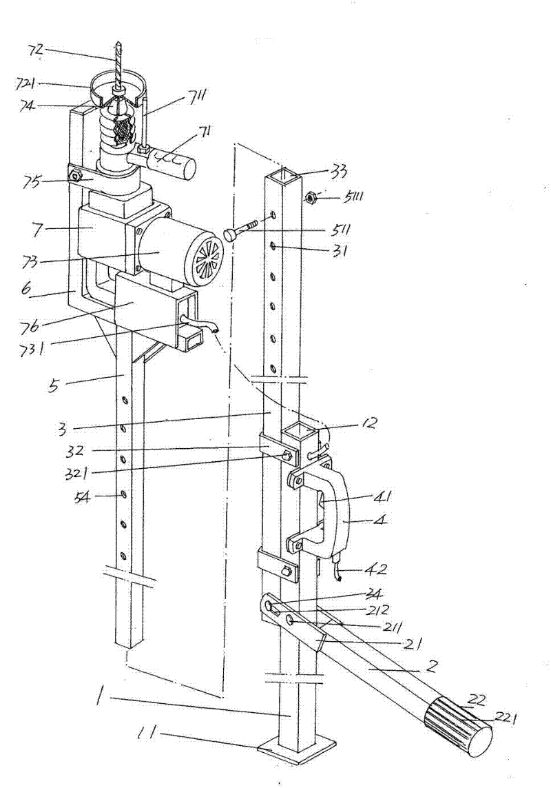
[0023] Please see figure 1 , a support tube 1 with a square cross-sectional shape and a hollow cavity 12 is provided, and a stabilizing plate 11 with a diameter larger than that of the supporting tube 1 is formed by expanding at the bottom of the support tube 1. The shape of the stabilizing plate 11 is both It can be square or disc-shaped, and the contact area between the support pipe 1 and the ground is increased by the stabilizing plate 11, thereby reflecting stability. A pressure bar handle 2 is hinged with the support tube 1, as shown in the figure, there is a pair of articulated arms 21 parallel to each other at the end of the support tube 2 towards the support tube 1, and the distance between the pair of articulated arms 21 is just 1, and a pair of articulated arms 21 can be made integrally with the pressure bar handle 2, and can also be fixed with the pressure bar handle 2 by welding, riveting or screws. In this embodiment, a pair of articulated arms 21 and the press...


PUM


Abstract

The invention discloses a floor type indoor ceiling concrete slab bottom drilling mechanism which belongs to the technical field of building indoor decoration construction instruments and comprising a supporting pipe, a pressure lever handle, an outer sleeve, a grip type power supply switch, an inner sleeve, a puncher bracket and a puncher, wherein the bottom of the supporting pipe is provided with a stabilizing plate; the pressure lever handle is connected to the supporting pipe; the upper part of the outer sleeve is provided with one group of outer sleeve regulating holes, the lower part ofthe outer sleeve is matched with the outer wall of the supporting pipe, the outer sleeve moves up and down when being adhered on the outer wall of the supporting pipe, the lower end part of the outersleeve is hinged with the pressure lever handle; the grip type power supply switch is fixed on the supporting pipe; the inner sleeve is accommodated in an outer sleeve cavity of the outer sleeve, theinner sleeve is provided with one group of inner sleeve regulating holes, when the inner sleeve regulating holes and the outer sleeve regulating holes are mutually coincided, the inner sleeve and theouter sleeve are locked by using an inner sleeve locking member; the puncher bracket is arranged at the top end part of the inner sleeve; and the puncher is fixed on the puncher bracket and is in electrical control connection with the grip type power supply switch. The floor type indoor ceiling concrete slab bottom drilling mechanism has the advantages of ensuring stability, having safety and light integral weight, being capable of adapting to different spatial heights and being convenient for movement.

Description

technical field [0001] The invention belongs to the technical field of building interior decoration construction equipment, and in particular relates to a floor-standing indoor ceiling concrete slab bottom drilling mechanism. Background technique [0002] As known in the industry, before the interior ceiling concrete slab bottom of industrial, commercial, public buildings and civil buildings is decorated and / or pipelines are laid, it is necessary to pre-fix the suspenders as transition parts to the bottom of the building. The concrete slab bottom of the indoor ceiling, and then the keel, pipeline and / or equipment (such as air conditioners, lamps, etc.) [0003] At present, the operation method of fixing the suspender to the bottom of the indoor ceiling concrete slab is all completed by suspended operation. The so-called suspended operation refers to the implementation of construction by means of ladders, scaffolding or work platforms. The operator climbs on a ladder, scaffo...

Claims


Application Information

Patent Timeline
IPC IPC(8): E21B15/00E21B21/015
Inventor 李国强张永生刘佩良陆建明朱卫兵
Owner 常熟市金龙装饰有限责任公司
Why Eureka
Eureka Blog
Learn More