A water seal drain

A drainer and water seal technology, which is applied in the pipeline system, mechanical equipment, gas/liquid distribution and storage, etc., can solve the problems of increasing the ground pipeline or equipment foundation height, no alarm device, messy pipeline, etc., to prevent system pressure Large-scale fluctuations, reduce labor intensity, and avoid the effects of messy venues

Inactive Publication Date: 2011-12-28
CISDI ENG CO LTD
View PDF3 Cites 3 Cited by
  • Summary
  • Abstract
  • Description
  • Claims
  • Application Information

AI Technical Summary

Problems solved by technology

[0004] 1. It takes up a lot of space, and the drains are all exposed above the ground. Each drain includes a cylinder, a water-sealed pipe and at least 3 interfaces. If there are multiple drainage systems, there will be many drains. On-site The pipeline is messy, the laying is complicated, and the area is large
[0005] 2. The initial investment is high. In order to achieve the sealing effect, a certain water seal height must be ensured. If it is installed on the ground, it will increase the height of the ground pipeline or equipment foundation, and equipment with large vibration will affect the stability of the system.
[0006] 3. High energy consumption. In severe cold, cold and hot summer and cold winter regions, in order to prevent freezing of water pipes and drains in winter, it is necessary to lay steam heat tracing or other methods along the pipes. Not only the drain itself consumes a lot of energy, but it is not conducive to energy saving and emission reduction
[0007] 4. Short service life
There is no alarm device, once the gas leaks, it will cause serious consequences, and the average service life of the steel drain is only 6 years

Method used


Image

  • A water seal drain
  • A water seal drain
  • A water seal drain

Examples


Embodiment Construction

[0032] The present invention will be further described below in conjunction with drawings and embodiments.

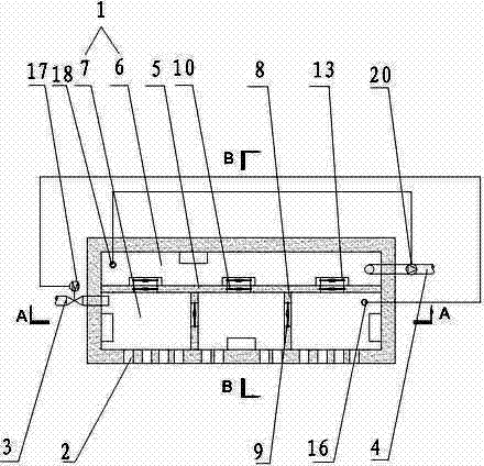
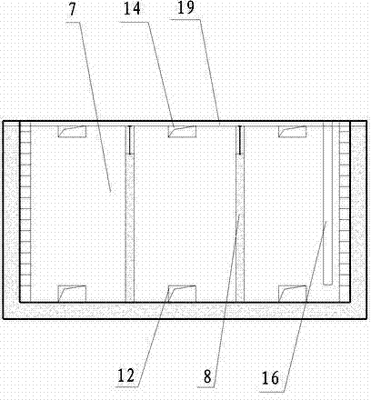
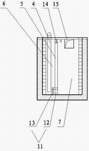
[0033] Such as figure 1 , figure 2 , image 3 As shown, a water-sealed drain includes a pool 1, a water inlet pipe 2, a water supply pipe 3 and a drain pipe 4, and a main partition wall 5 is arranged in the pool 1 to separate the pool 1 into drainage pools that do not communicate with each other. 6 and the water seal body, the replenishment pipe 3 passes through the pool 1 and leads to the water seal body, the drain pipe 4 passes through the pool 1 and leads to the drainage pool 6, the water seal body includes a plurality of water seal pools 7, adjacent water seal The pools 7 are separated into separate independent units by water-sealed partition walls 8, and multiple water inlet pipes 2 pass through the side walls of the pools 1 and lead to each water-sealed pool 7, at the top of each water-sealed partition wall 8 Both overflow devices 9 are provided, and a plural...


PUM


Abstract

The invention discloses a water lute drainer which comprises a pool, water inlet pipes, a water replenishing pipe and a drain pipe. The water lute drainer is characterized in that a main partition wall is arranged in the pool so as to separate the pool into a drain tank and a water seal body which are not communicated, and the water replenishing pipe passes through the pool so as to be communicated with the interior of the water seal body; the drain pipe passes through the pool so as to be communicated with the drain tank, the water seal body comprises multiple water seal pools, and water seal partition walls are used for separating the adjacent water seal pools into separate units which are not communicated; multiple water inlet pipes pass through the side wall of the pool and are communicated with each water seal pool, and the top of each water seal partition wall is provided with a water overflowing device; and the main partition wall is provided with multiple drainage devices which are communicated with the water seal pools and the drain tank, and the height of the water overflowing device is lower than that of the drainage devices. The water lute drainer provided by the invention has the advantages that multiple water seal pools share a set of equipment, the structures of the multiple drainage devices are simplified, and the occupied space is obviously reduced.

Description

technical field [0001] The invention relates to a drainer, in particular to a gas system waste water discharge device. Background technique [0002] During the transportation or treatment of dangerous gases in metallurgy, chemical industry, petroleum, natural gas and other industries, part of the water vapor will inevitably condense continuously as the gas flow rate and temperature decrease, resulting in a large amount of condensed water in the gas pipeline; or for cleaning The fan impellers, valves, etc. that transport and pressurize the above-mentioned gases are washed with water, etc., and the SO contained in them 4 2- , Cl - 、H 2 S, etc. will cause strong chemical corrosion and electrochemical corrosion to metal components, and the dust contained will scale in pipes and equipment. In order to ensure the safety of the system, various drainers are widely used to automatically discharge corrosive waste water such as condensed water and flushing water. [0003] For the ...

Claims


Application Information

Patent Timeline
Patent Type & Authority Applications(China)
IPC IPC(8): F17D3/14
Inventor 桑杭武梁广杨俊
Owner CISDI ENG CO LTD
Why Eureka
Try Eureka