A stereoscopic lens for an ordinary camera or video camera

A technology of cameras and video cameras, applied in stereophotography, photography, instruments, etc., can solve the problems of loss of viewing angle, high equipment cost, poor portability, etc., and achieve the effect of reducing volume and weight

Inactive Publication Date: 2011-12-28
韩松
View PDF2 Cites 17 Cited by
  • Summary
  • Abstract
  • Description
  • Claims
  • Application Information

AI Technical Summary

Problems solved by technology

[0003] Using a stereo camera (or stereo camera), the imaging effect is good, but the equipment cost is high, and the versatility with traditional photographic (or video) equipment is poor; two (or more) single-lens cameras (or single-lens cameras) are used for transformation, imaging The effect is good, but the equipment cost is high, the system is complicated, the volume and weight are large, and the portability is poor, and it is difficult to realize the synchronization of two devices. The method of moving the ordinary camera (or video camera) left and right is used for shooting, and the control of the moving distance and shooting angle It is very difficult, and the shooting time is not synchronized, and the imaging effect is poor
[0004] Adopting the tradi...

Method used


Image

  • A stereoscopic lens for an ordinary camera or video camera
  • A stereoscopic lens for an ordinary camera or video camera
  • A stereoscopic lens for an ordinary camera or video camera

Examples


Embodiment Construction

[0025] In order to make the object, technical solution and advantages of the present invention clearer, the present invention will be described in further detail below in conjunction with specific embodiments and with reference to the accompanying drawings.

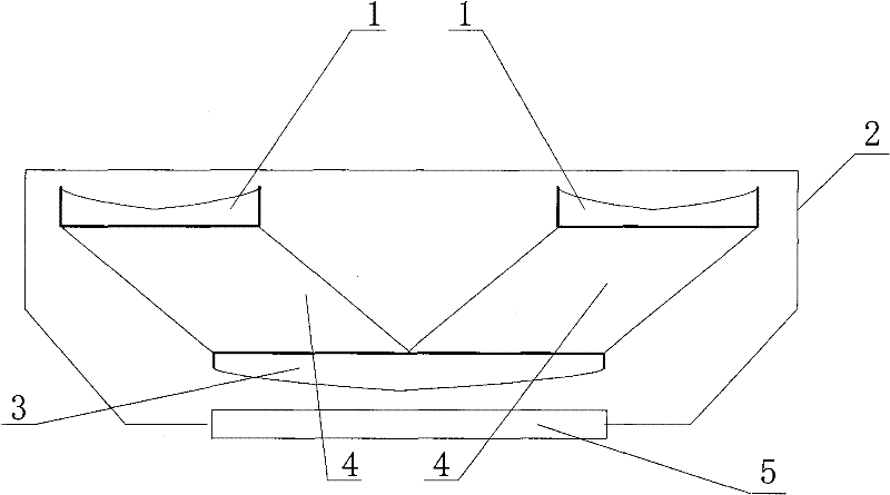
[0026] Such as figure 1 Example 1 shown, figure 1 It is a horizontal sectional view of a stereoscopic lens that adopts a rhombic prism provided by the present invention, including a housing 2, a diverging lens (or lens group) 1 of the left and right optical paths, a rhomboid prism 4 of the left and right optical paths, and a splicing and converging lens (or lens group) 3 , the threaded interface 5 connected with the camera (or video camera).

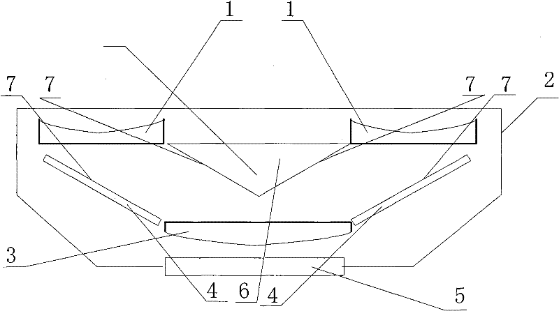
[0027] Such as figure 2 Example 2 shown, figure 2 It is the horizontal sectional view of the stereo lens of the reflecting mirror group that adopts two plane reflecting mirrors to form provided by the present invention, comprises housing 2, the diverging lens (or lens group) 1 ...


PUM


Abstract

The present invention is a stereoscopic lens added in front of the lens of a common camera (or video camera), and is used for obtaining binocular stereoscopic images. Compared with the conventional additional stereo lens, the viewing angle range of the camera (or video camera) can be maintained while reducing the size and weight of the additional lens. The present invention adopts two groups of optical assemblies corresponding to the left eye optical path and the right eye optical path of binocular stereoscopic imaging, each optical path includes a diverging lens (or lens group), a rhomboid prism (or a mirror group composed of two plane mirrors) , Splicing and converging lenses (or lens groups), to achieve compressed viewing angle, parallel light transmission, translation, widening viewing angle, left and right image splicing, and finally realize the splicing of the two images of the left eye optical path and the right eye optical path into one image, and then enter the camera ( or camera) to obtain an image containing stereoscopic information.

Description

technical field [0001] The present invention relates to the field of stereo photography, in particular to binocular stereo photography and imaging equipment, utilizing existing single-lens photography equipment or systems (such as ordinary cameras, ordinary video cameras), by adding an additional device (i.e. an additional stereo lens) in front of the lens to obtain Binocular stereo imaging information. Background technique [0002] Stereo photography is a photographic method that expresses the three-dimensional space of the scene. By shooting two images from different viewpoints, simulating binocular viewing to achieve a three-dimensional effect. The shooting tools of stereo photography include special stereo cameras (or stereo cameras); there are also stereo attachment mirrors assembled on single-lens cameras (or single-lens cameras); there are also two (or more) single-lens cameras (or single-lens cameras) Carry out transformation, make two equipments shoot synchronously...

Claims


Application Information

Patent Timeline
IPC IPC(8): G02B27/22G03B35/10
Inventor 韩松
Owner 韩松
Why Eureka
Try Eureka