Data Access Method for Multi-source Data Acquisition

A data access, multi-source data technology, applied in electrical components, circuit devices, etc., can solve problems such as heavy workload, lack of flexibility, rigid data acquisition system structure, etc., to reduce construction costs and development.

Inactive Publication Date: 2011-12-28
NARI NANJING CONTROL SYST
View PDF3 Cites 8 Cited by
  • Summary
  • Abstract
  • Description
  • Claims
  • Application Information

AI Technical Summary

Problems solved by technology

In the face of this situation, for a long time, the construction of the data acquisition system first builds its own data acquisition channels according to different protocols and acquisition terminals of different factories and stations, and then integrates them. The structure of the data acquisition system built in this way is rigid, lacks flexibility, and cannot Conducive to the unified management of different data sources
When a new acquisition channel is added, the entire system may need to be re-planned, with a huge workload

Method used


Image

  • Data Access Method for Multi-source Data Acquisition
  • Data Access Method for Multi-source Data Acquisition

Examples


Embodiment 1

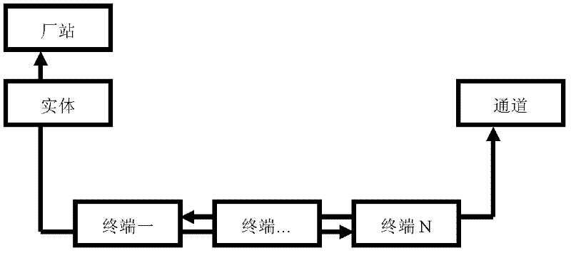
[0048] A group contains a factory station, and two data entities are configured under a factory station, which are respectively recorded as entity 1 and entity 2, and then two channels are configured under the pre-group, which are respectively recorded as channel 1 and channel 2. Configure two data acquisition terminals, which are respectively recorded as terminal 1 and terminal 2. Configure the channel to which terminal 1 belongs to channel 1, the entity to which it belongs to entity 1, the channel to which terminal 2 belongs to channel 2, and the entity to which terminal 2 belongs to entity 2. Thus, the data of entity 1 of the plant station is collected by terminal 1 via channel 2, and the data of entity 2 is collected by terminal 2 via channel 2.

[0049] This embodiment is suitable for multi-source data collection.

Embodiment 2

[0051] The difference between this embodiment and Embodiment 1 is that one data entity is configured under one plant station, and one channel is configured under the pre-group to which the plant station belongs. Configure multiple data collection terminals to belong to this entity and this channel. This embodiment is suitable for multi-point collinear data collection of distribution network.

Embodiment 3

[0053] The difference between this embodiment and Embodiment 1 is that two factory stations are configured under one pre-group, which are respectively factory station 1 and factory station 2. Data entity 1 is configured under factory station 1, and data entity 2 is configured under factory station 2. . Then, two channels are configured under the pre-group, which are respectively channel one and channel one, and two data collection terminals are respectively configured as terminal one and terminal two. Configure the channel to which terminal 1 belongs to channel 1, the entity to which it belongs to entity 1, the channel to which terminal 2 belongs to channel 2, and the entity to which terminal 2 belongs to entity 2. The data of station one is collected by terminal one through channel one, and the data of station two is collected by terminal two through channel two. This embodiment is applicable to the unified access of multiple collection channels of different stations, differ...


PUM


Abstract

The invention discloses a data access method for multi-source data collection, which is characterized in that it includes the following steps: 1) defining the following data sets, including groups, stations, entities, channels and terminals; 2) extracting different stations and channels and information, according to the predetermined grouping standard, pre-group different stations and channels; 3) the original data directly collected by the communication terminal device; 4) the channel uses the transfer function to transfer the original data to the terminal; 5) the terminal The data exists in the entity, the plant, and the group, and the group will integrate the collected data into the integrated automation system of the power system. The present invention can connect multiple channels of different data sources, different communication terminals, and different communication protocols in different plants and stations to the comprehensive automation system of the power system, avoiding the situation of configuring different acquisition systems for different data acquisition channels, reducing The construction cost of the data acquisition system is reduced.

Description

Technical field [0001] The present invention involves a dynamic allocation and grouping method of poly source data collection. Background technique [0002] With the development of economic construction, the pace of comprehensive automation construction in my country's power system has continued to accelerate.Data collection is a key component of comprehensive automation.The power system itself is a very complicated system. The number of equipment is huge, there are many types, and the regional distribution is wide.Terminal access.In the face of this situation, the construction of the data collection system for a long time first builds their respective data collection channels according to different plants and stations and collects terminal construction, and then integrated.Conducive for unified management of different data sources.When a new collection channel is added, the entire system may need to be re -planned, and the workload is huge.With the continuous development of the ...

Claims


Application Information

Patent Timeline
Patent Type & Authority Applications(China)
IPC IPC(8): H02J13/00
Inventor 朱守让王伟张韬邵宇陈斌
Owner NARI NANJING CONTROL SYST
Why Eureka
Try Eureka