Baffle plate in stirring tank

A stirring tank and baffle technology, which is applied to mixer accessories, mixers with rotating stirring devices, mixers, etc., to achieve the effects of improving mixing efficiency, reducing energy consumption of baffles, and eliminating over-baffles

Inactive Publication Date: 2012-01-04
CHONGQING UNIV
View PDF6 Cites 7 Cited by
  • Summary
  • Abstract
  • Description
  • Claims
  • Application Information

AI Technical Summary

Problems solved by technology

However, because the baffles in the "Stirred Reactor with Slotted Baffles" have something in common with other prior art, that is, each baffle is a single piece, from the upper end of the baffle to the lower end of the baffle. In the ent

Method used


Image

  • Baffle plate in stirring tank
  • Baffle plate in stirring tank
  • Baffle plate in stirring tank

Examples


Example Embodiment

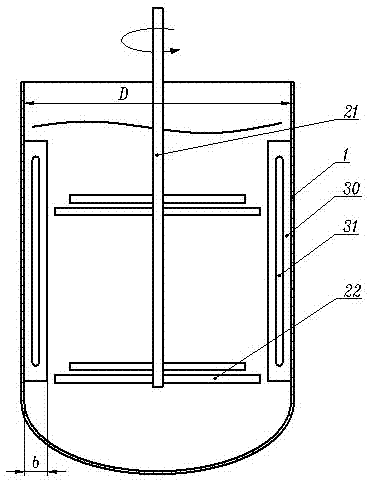
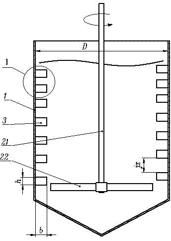
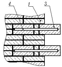
[0010] A baffle in a stirring tank (reference figure 2 ), the baffles are arranged on the inner wall of the stirring tank 1 in the form of being evenly distributed in two to four places, and are parallel to the rotating shaft 21 of the stirring blade in the stirring tank 1; the width of each baffle b All are the inner diameter of the stirring tank D 1 / 12~1 / 10 of. In the present invention, each baffle is a baffle group composed of several small baffles 3 arranged with a gap between each other; the height of each small baffle 3 h Its width b 1 / 2~2 / 3, the gap between two adjacent small baffles 3 jx 3 height for small baffle h 1 to 2 times as much.

[0011] From the disclosure up to this point, those skilled in the art, combined with their understanding of the principle of the beneficial effects of the present invention, can already manufacture baffles in the agitating tank that are essentially the same as those of the present invention according to other different conditions and / or r...


PUM


Abstract

The invention discloses a baffle plate in a stirring tank. The baffle plates are uniformly distributed between two and four places and arranged on the inner wall of the stirring tank and are parallel to a rotating shaft of stirring blades in the stirring tank, and the width of each baffle plate is 1/12-1/10 of the inner diameter of the stirring tank. Each baffle plate disclosed by the invention is a baffle plate group formed by arranging a plurality of small baffle plates at intervals, the height of each small baffle plate is 1/2-2/3 of the width of the small baffle plate, and a gap between every two adjacent small baffle plates is 1-2 times the height of each small baffle plate. The baffle plate is characterized in that a standard baffle plate is slit into a plurality of sections and the gaps are preserved by picking one part at intervals. Compared with the baffle plate with a slit, the baffle plate is equivalent to the baffle plate with the slit on the aspects of improving the mixing effect and efficiency, but has the advantage of reducing the energy consumption greatly, and has better energy-saving and consumption-reducing effects.

Description

technical field [0001] The invention relates to a mechanical stirring tank with baffles commonly used in the production process of chemical products. Background technique [0002] Mechanical stirring is an operation step often used in the production process of many chemical products. The stirred reactor is the most commonly used equipment to realize this mechanical stirring. Its traditional structure includes a stirring tank containing fluid materials (mixed liquid or mixed slurry), vertically arranged The rotating shaft in the middle of the stirring tank and the paddles fixed on the rotating shaft (the rotating shaft and the paddles, collectively referred to as stirring paddles). In order to eliminate the "vortex" generated by the liquid surface of the fluid material in the traditional mixing tank as much as possible, to avoid the accident of the fluid material overflowing the mixing tank, and to overcome the overall movement of the fluid material caused by the "vortex", wh...

Claims


Application Information

Patent Timeline
IPC IPC(8): B01F7/18B01F15/00
Inventor 刘作华宁伟征陶长元彭浩周小霞刘仁龙曾启琴杜军范兴孙瑞祥廖军李泽全谢昭明孙大贵
Owner CHONGQING UNIV
Why Eureka
Try Eureka