
Supersonic velocity spray pipe with shared throat part and design method of supersonic velocity spray pipe

A design method and supersonic technology, applied in the direction of injection device, injection device, etc., can solve the problems that the flow field quality of supersonic/hypersonic nozzle can not meet the test requirements well, and it is difficult to generate flow field test conditions with different parameters, etc. Achieve the effect of saving processing costs, improving quality and ensuring uniformity

Active Publication Date: 2012-01-04
NAT UNIV OF DEFENSE TECH
View PDF1 Cites 18 Cited by
  • Summary
  • Abstract
  • Description
  • Claims
  • Application Information

AI Technical Summary

Problems solved by technology

[0008] The present invention aims to provide a supersonic nozzle with a shared throat and its design method, so as to solve the problem of flow field test conditions that are difficult to generate different parameters in the prior art, and the flow field quality of the designed supersonic / hypersonic nozzle cannot be satisfied. Very good question that satisfies the test requirements

Method used


Image

  • Supersonic velocity spray pipe with shared throat part and design method of supersonic velocity spray pipe
  • Supersonic velocity spray pipe with shared throat part and design method of supersonic velocity spray pipe
  • Supersonic velocity spray pipe with shared throat part and design method of supersonic velocity spray pipe

Examples


Embodiment Construction

[0046] Hereinafter, the present invention will be described in detail with reference to the drawings and examples. It should be noted that, in the case of no conflict, the embodiments in the present application and the features in the embodiments can be combined with each other.

[0047] In the present invention, the subsonic section refers to the part where the flow velocity of the airflow is less than the speed of sound after entering the constriction section of the nozzle, and the subsonic section is also the transonic section, which refers to the junction between the airflow entering the supersonic state from the subsonic state, Generally, the Mach number in the subsonic section is less than 0.8, the Mach number in the subsonic section is between 0.8 and 1.2, and the Mach number in the supersonic section is greater than 1.2.

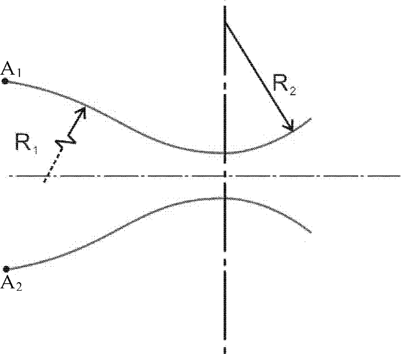
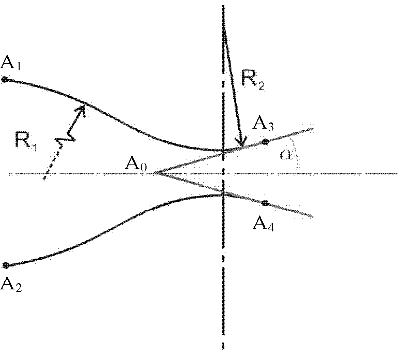
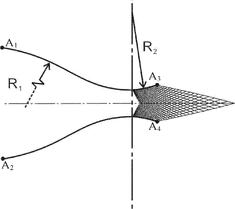
[0048] Such as figure 1 As shown, according to the supersonic nozzle design method of the shared throat of the present invention, firstly, accordin...


PUM


Abstract

The invention provides a supersonic velocity spray pipe with a shared throat part and a design method of the supersonic velocity spray pipe. The design method of the supersonic velocity spray pipe with the shared throat part comprises the following steps of: determining a subsonic velocity segment curve according to an entrance geometric parameter and the area of the throat part; determining an initial characteristic line emitted from the throat part according to the subsonic velocity segment curve and the maximum divergence angle; determining a curve of a wall surface in the shared segment of the throat part by a characteristic line method according to the initial characteristic line and the mach number of the wall surface in the shared segment of the throat part; and setting the mach number distribution of an axial line in the downstream of the curve on the wall surface in the shared segment of the throat part according to the structural design requirement of the supersonic velocitysegment of the spray pipe, and determining a non-throat part curve in an iteration way by the characteristic line method. By the design method, the parameter of an exit flow field of the spray pipe can be changed by sharing the throat part and exchanging an expansion segment; the processing cost of the throat part of a wind tunnel spray pipe is saved; and the uniformity of the exit flow field of the spray pipe can be ensured and the quality of a wind tunnel flow field can be improved while the throat part is shared. According to the supersonic velocity spray pipe with the shared throat part, the design method of the supersonic velocity spray pipe with the shared throat part is utilized.

Description

technical field [0001] The invention relates to the field of fluid power, in particular to a supersonic nozzle with a shared throat and a design method thereof. Background technique [0002] Supersonic / hypersonic nozzles are widely used in high-speed aircraft, rocket engines, supersonic wind tunnels, high-energy lasers, ejector vacuum pumps and other equipment. The quality of the nozzle flow field has an important impact on the performance of the equipment. Obtaining an appropriate nozzle wall curve through certain design techniques can greatly improve the quality of the nozzle flow field, improve equipment performance, and save research funds. A supersonic nozzle generally consists of a converging section (subsonic section) and an expanding section (supersonic section). Driven by a certain pressure, the gas gradually accelerates in the converging section and reaches the speed of sound near the throat, and then continues to accelerate in the expansion section until a supers...

Claims


Application Information

Patent Timeline
Patent Type & Authority Applications(China)
IPC IPC(8): B05B1/34
Inventor 赵玉新易仕和王振国沈赤兵
Owner NAT UNIV OF DEFENSE TECH
Learn More