Reinforcing rib making die for ribbed superposed concrete prefabricated member

A prefabricated component and concrete technology, applied in the mold and other directions, can solve the problems of time-consuming and labor-intensive demoulding treatment and operation, poor standardization and interchangeability of reinforcing rib molds, cumbersome disassembly and assembly, etc. Effect

Active Publication Date: 2012-01-04
SHANDONG ONE STAR CO NSTRUCTION TECH CO LTD
View PDF7 Cites 1 Cited by
  • Summary
  • Abstract
  • Description
  • Claims
  • Application Information

AI Technical Summary

Problems solved by technology

[0008] The object of the present invention is to provide a reinforcing rib manufacturing mold for a ribbed composite prefabricated concrete component, which can solve the problem of poor standardization and interchangeability of the reinforcing rib mold existing in the prior art, and cannot meet the needs of industrialized production of concrete prefabricated parts. And the problems of cumbersome disassembly, demoulding and time-consuming operation

Method used


Image

  • Reinforcing rib making die for ribbed superposed concrete prefabricated member
  • Reinforcing rib making die for ribbed superposed concrete prefabricated member
  • Reinforcing rib making die for ribbed superposed concrete prefabricated member

Examples


Embodiment 1

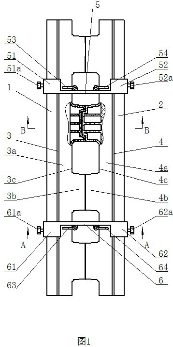
[0042] In the present invention, the concrete prefabricated thin slab is manufactured industrially on the production line by means of a concrete distributing machine. The thickness of the thin slab is 30mm, and according to the operating regulations, the reinforcing rib mold is placed and assembled on the concrete prefabricated thin slab within a specified time before the concrete is solidified. That is: the first elastic lining film 3 and the second elastic lining film 4 are respectively installed on the inner side walls of the first template 1 and the second template 2, and the first lower lining film 3a of the first elastic lining film 3 is sleeved on the second On a horizontal plate body 1a, the second lower lining film 4a of the second elastic lining film 4 is set on the second horizontal plate body 2a, and the first baffle plate 5 and the second baffle plate 6 are respectively arranged on the first template 1 , between the second template 2, and make the first baffle plat...

Embodiment 2

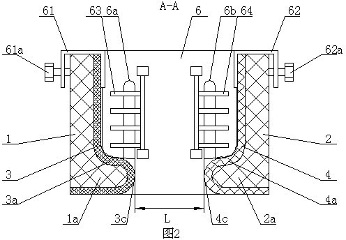
[0050]The present invention also can adopt the first baffle plate 5 and the second baffle plate 6 that offer several reinforcement holes in the vertical direction, the reinforcing bar holes that vertical direction arranges on the first baffle plate 5 and the vertical direction arrangement on the second baffle plate 6 respectively. The steel bar holes correspond one to one, to replace the comb-shaped first steel bar bracket 53, the second steel bar bracket 54, the third steel bar bracket 63 and the fourth steel bar bracket 64, several steel bars that are set up in the vertical direction The holes can also support each steel bar on each layer of steel bars arranged up and down, and can also meet the needs of different sizes of reinforcing ribs and the number of steel bars arranged in the mold, and can also prevent the steel bars from being prestressed in the mold. time mutual dislocation.

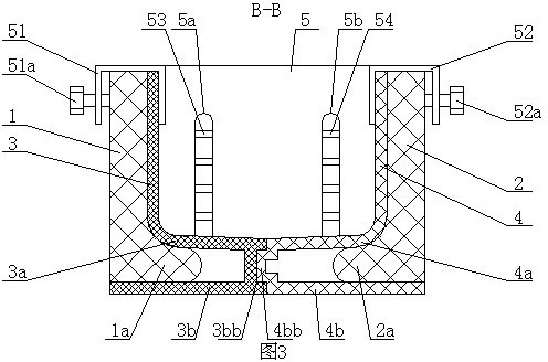
[0051] The first convex part 3b and the second convex part 4b of the present invention ma...


PUM


Abstract

The invention discloses a reinforcing rib making die for a ribbed superposed concrete prefabricated member. The die comprises a first template and a second template which are arranged corresponding to each other; the sections of the first template and the second template respectively consist of a vertical plate body and a horizontal plate body positioned at the lower part of the vertical plate body and are L-shaped; a first elastic lining film and a second elastic lining film are respectively arranged on the inside walls of the first template and the second template; the mutually corresponding edges of the first lower lining film and the second lower lining film are respectively concave-convex; a first baffle plate and a second baffle plate are respectively arranged between the first template and the second template and are respectively in contact with the first elastic lining film and the second elastic lining film; the first baffle plate is provided with a first steel bar hole and asecond steel bar hole; and the second baffle plate is provided with a third steel bar hole and a fourth steel bar hole. The die has the remarkable characteristics of standardization, strong interchangeability, simplicity and convenience in disassembly and assembly, no need of die release treatment and capability of meeting industrialized production of concrete prefabricated members.

Description

technical field [0001] The invention relates to the technical field of concrete member molds, in particular to a mold for making reinforcing ribs of a ribbed composite concrete prefabricated member. Background technique [0002] When the construction industry is carrying out the construction of multi-storey buildings, the floor slabs between each floor and the roof slabs on the top floor of the building are mostly in the form of in-situ pouring concrete to achieve the integrity of the floor slabs and roof slabs to ensure the integrity of the building. Earthquake resistance and safety quality. [0003] At present, when the traditional technology is used for this construction, a large number of formwork is manually assembled into a floor mold at the construction site, and the mold is supported by a large amount of supporting materials, and then the concrete is poured on site to make the floor slab and the roof. Board, floor slab and roof slab are removed formwork and supporti...

Claims


Application Information

Patent Timeline
IPC IPC(8): B28B7/22
Inventor 张波朱彤
Owner SHANDONG ONE STAR CO NSTRUCTION TECH CO LTD
Why Eureka
Try Eureka